This thread has been locked.

If you have a related question, please click the "Ask a related question" button in the top right corner. The newly created question will be automatically linked to this question.

UCD3138PSFBEVM-027: Designing a UCD3138 Controlled PSFB

Part Number: UCD3138PSFBEVM-027
Other Parts Discussed in Thread: UCD3138,

Hello,

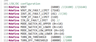
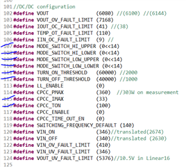
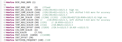
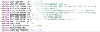
I am working on dc-dc converter (400V to 48V ; 2.5kW) and trying to reuse the UCD3138PSFBEVM-027 module and concept that uses UCD3138 digital controller. Currently the EVM is deigned for 400V to 12 V ; 600W. I am kind of clear with the baseboard changes with respect to my requirement. Kindly let me know what changes I need to do with respect to firmware (reference sluc614) as I am new to the digital controller concept.What are the steps that needs to be followed.

Thanks and Regards,

Priya Sinha

  • Hello,

    Input is the same as EVM's input, the difference is output voltage and output power. Here are changes I could think of:

    1. Transformer turns ratio;

    2. Output voltage sensing circuit:  The max input to UCD3138 EAP0 is 1.6V; The max input to UCD3138 AD03 is 2.5V;

    3. Output current sensing circuit, and make sure the max output doesn't go beyond the limit;

    4. In Firmware, output voltage setting need be changed from 12V to 48V

    5.  In Firmware, protection such as OVP, OCP, CBC limit need be changed.

    I hope this can help,

  • Hello,

    Thanks for the above information. I further want to ask:

    1. Changes required in firmware with respect to compensation (Kp,Ki,Kd to get suitable PM,GM and crossover).

    2. Which part/file of the code in CCS needs to be modified.

    Thanks and Regards

    Priya Sinha

  • Hello,

    You can make changes in the file pmbus_topology.h. For your board, I am not sure what number should be used, and you had better figure out on your side.  If you have a specific question, I can help you.

    Thanks,

    Sean

  • Hello,

    In  pmbus_topology.h under DC-DC congiguration, VOUT is defined as 6080 and similarly for others. May I know what does that represent? As per my knowledge it is supposed to be 12V.

    Thanks and Regards,

    Priya

  • Hi,

    The formula to calculate VOUT is: output voltage setting * (2^VOUT_MODE_EXP), VOUT_MODE_EXP =9, PMBUs standard.

    for example, at 12V, VOUT = 12 *512 = 6144.  To get more accurate output, VOUT is tuned at 6080.

  • Hello,

    Thanks for the above explanation. Needed clarification on some more points:

    1. Kindly let me know the meaning/requirement of the marked parameters in Capture.png.

    2. Is there any change that is required in system_defines.h file or the changes alone in pmbus_topology.h is sufficient with firmware perspective.(system_defines.PNG, system_defines_1.PNG, system_defines_2.PNG).

    Thanks and Regards,

    Priya Sinha

  • Hello,

    MODE_SWITCH_HI_UPPER, MODE_SWITCH_HI_LOWER, MODE_SWITCH_LOW_UPPER, MODE_SWITCH_LOW_LOWER are used for setting mode switching thresholds. Now the setting is 0, so the mode switching is disabled.

    TURN_ON_THRESHOLD  and TURN_OFF_THRESHOLD are used for setting burst mode  thresholds. When voltage loop output is higher than 60000, DPWMs are turned on, and when voltage loop output is lower than 40000, DPWMs are turned off.

    CPCC_IMAX and CPCC_ON are not used in the code.  They are used for constant current and constant power control.

    Regards,

  • Hello,

    Thanks for the above explanation. I also wanted to now Is there any specific change that is required in system_defines.h file? 

    Thanks and Regards,

    Priya

  • I think you need make some changes accordingly if you make hardware changes to sense output voltage, current, as shown above.

  • Hello, 

    As mentioned above about TURN_ON_THRESHOLD  and TURN_OFF_THRESHOLD, The voltage level mentioned is 60000 and 40000, I wanted know what actual value of voltage it represents and how those (60000, 40000) values are calculated so that I could calculate for my requirement.

    Thanks and Regards

    Priya

  • Hello,

    For current mode control, voltage loop output is current reference or command, 60000 is converter to voltage on the pin EAP2 (CS pin), the voltage is 1.56mV * 60000/256 = 365mV.  40000 corresponds to 243mV roughly.

    For voltage mode control, voltage loop output is PWM on time. With 60000, on time is 60000 *0.25ns = 15us.

    TI EVM is current mode control, the first case is applied.

  • Hello,

    Thanks for the above explanation. I wanted to know, since it is controller input parameter at EAP2 pin. Will those values (60000 and 40000 ) change?

    According to above statement, EAP2 is used for external compensation and the voltage level should be maintained above 100mV. So kindly let me know if the values (60000 and 40000) will remain same or be changed when my output requirement changes from 12V to 48V. If it has to be changed what will be the approximate value?

    Thanks and Regards

    Priya

  • Hello,

    60000 or 40000 are not fixed number. the absolute number just affect at which load output voltage starts to burst.

  • Hello,

    Thanks for the information.

    I further want to ask about how the values in the box (in attached png) calculated? Is there any specific document related to firmware that helps in understanding all calculations and logics behind them?


    Thanks and Regards,

    Priya Sinha

  • Hello,

    The formula are given in the comments after two /s. 

    For example, VOUT_AD12_SCALER.   it means what is ADC LSB when VOUT is changed for 1V.

    so: 1V * (R1/(R1+R2)) /2.5V * 4096.

    R1, R2 are voltage VOUT divider . R1/(R1+R2) = 0.1 from EVM hardware

    2.5V is full scale

    4096 is 12bit ADC result.

    you can get 165, then tuned to 167.

    You can calculate other scalers. 

    Regards,

  • Hello,

    Thanks for the above calculations. I was able to calculate many of them but still stuck with few:

    1. IOUT_DAC_SCALER

    2. IIN_COMP_SCALER

    3. VIN_SCALER

    4. POUT_SCALER

    5. IOUT_OFFSET

    6. IOUT_OC

    7. IOUT_NO_OC

    Kindly let me know the calculations for the above parameters so that I can make changes according to my requirement.

    Thanks and Regards,

    Priya Sinha

  • Hello,

    1. IOUT_DAC_SCALER.   From the schematic, R1 = R75 - 3.32k; R2 = R74 = 2k,  DAC full scale is 14 bit @1.6V.  Amplifier gain is 0.0549

    IOUT_DAC_SCALER= 3.32/ (3.32 + 2) * 0.0549 * 2^14 / 1.6  = 350.

    2. IIN_COMP_SCALER It is used for COMPARATOR_F (AD06) CBC protection. There is no equation for this number.

    3. VIN_SCALER. The number is based on the measurement from auxiliary supply. When Vin  is changed by 1V, the ADC is changed by  7.73 This is an averaged number.

    4. POUT_SCALER. =it is equal to VOUT_ADC_SCALER * IOUT_ADC_SCALER = 167* 90 =15030. With some tuning, it is defined as 14850.


  •  5. IOUT_OFFSET is offset from amplifier, and tuned number.

    6. IOUT_OC. Set over current threshold by ADC sensing.  Iout shut down is 43.3A (=3900/90).

    7.  IOUT_NO_OC. Set recovery threshold. 3860 /90 = 42.8A.  

    OC protection is done in the Comparator_E (AD13). ADC OC protection threshold is hard coded here.

  • Hello,

    Thanks for clarifying above parameters.

    In case of IOUT_OC and IOUT_NO_OC the current values are taken as 43.3A and 42.8A respectively. The actual output current is 30A (360/12=30A).

    My actual requirement i.e 52A  (2500/48= 52A), so accordingly these values must change. Kindly let me know if the values are obtained from simulation or an approximate value of around 60A is ok.

    Also Kindly clarify if the statement ''OC protection is done in the Comparator_E (AD13). ADC OC protection threshold is hard coded here.'' is for IOUT_OC and IOUT_NO_OC, then can these values be altered according to my requirement as you have mentioned that these are hard coded.

    Thanks and Regards,

    Priya Sinha

  • Hello,

    60A is reasonable. You may need hardware change. Increase voltage divider after current amplifier so that there is less voltage to AD13.  The max voltage to ADC12 is 2.5V.