This thread has been locked.

If you have a related question, please click the "Ask a related question" button in the top right corner. The newly created question will be automatically linked to this question.

TLV733P: LEAKAGE ISSUE URGENT

Part Number: TLV733P

Hi team,

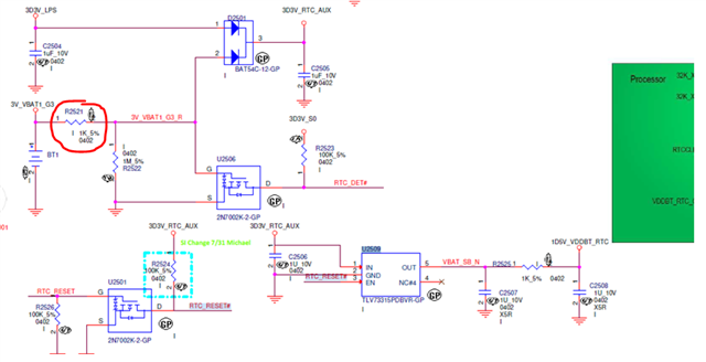
my customer discover large leakage (1mA) at Vin of TLV73315 during "coin battery supply",

as you can see below the red circle, when they decrease the resistor value,  the leakage disappear,

also when they use adapter input ( another diode's input) ,  no leakage occur miraculously.

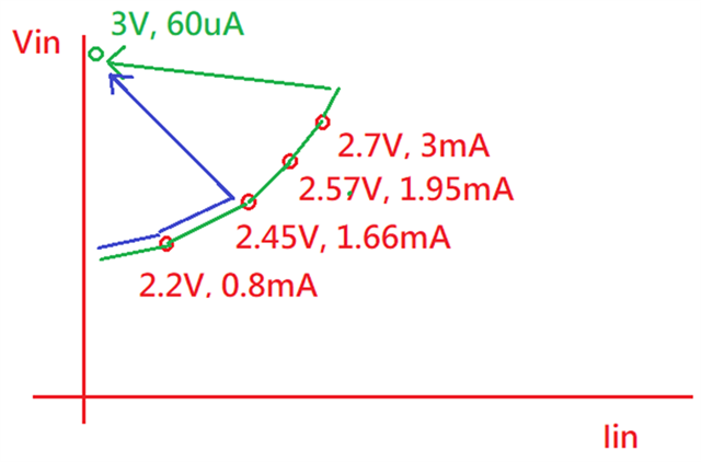
does this has something to do with the RC between battery and vin during power up?  (R=1Kohm, C=2uF )

BTW,  they also use p2p source TPS7A0515,  and unlike TLV73315 they see no issue at all.

  • Hi Fred,

    I am trying to understand why the customer has R2521 and R2525 in the power path. With a coin cell application (i.e. limited supply energy) this will just burn extra power. 

    You said that this leakage is only happening at startup? Is it inrush current or is it persistent leakage?

    Do they have any scope shots of this happening? 

    Thanks,

    Nick

  • Hi Nick,

    I don't know the meaning of R2521 and R2525 either, but they want to find the root cause now even so.

    the leakage is not just observed at startup, it's persistent according to them. but I think it caused by startup

    they use volt-multimeter to calculate the voltage across the R2521, to calculate the leakage current.

    they expected to see 60uA through R2521 according to datasheet, but instead they saw 1mA across it.

    my personal speculation is that during startup , since there's a RC at battery,

     IC enable before the Vin charge up  to be 3.3V, so it sink unexpected large current ,  it somehow create balance that Vin  voltage can't charge up to 3.3V,

    since the charging current are all sink by LDO  . does this make sense?

  • Hi Fred,

    Did they measure the output of the LDO while the leakage is about 1mA? Does it get up to the 1.5V that it is expected to reach?

    Are you saying that the LDO is enabled right as the battery is plugged in? 

    Here's what I think is happening. If the input to the LDO (3D3V_RTC_AUX) is not charged to 3.3V when the LDO is enabled, the LDO will take what charge is at its input and send it to the output to begin turning on the output. This will drain the input capacitor, and the UVLO point might be crossed and turn the LDO back off. The "P" in the nomenclature for this device means it has an active discharge circuit, so when the LDO is turned off it loses any charge that was already on the output and it will have to start over again. If the input is never allowed to charge all the way before the LDO turns on then this might keep happening and the LDO can never turn all the way on.

    Regards,

    Nick

  • Hi Nick,

    I've engage with TLV73315P  RD more , let's skip TLV74315P here before I receive more evidence, but I assume they might be similar issue here,

    below is what I got regarding TLV73315 , and yes the vout is 1.5V

    as you can see they try different R2521 value,  for example (2.7V, 3mA) is 100ohm , and when they try to use lower than 100ohm

    it just came back to 60uA miraculously (green line)

    regarding your theory may be an option, since TPS7A0515 doesn't have discharge function right?

    But the TPS73315 Vin above is all above UVLO threshold 1.3V, so might not fit in your thoeory?

  • Hi Fred,

    Well if the output is stable at 1.5V and there is still leakage then it doesn't matter if there is an active discharge circuit and my theory doesn't work. 

    In the diagram that you shared, is the Vin the direct input to the LDO? 

    Have they measured the output impedance of the coin cell? I've seen in the past that these batteries can have a couple kilo-ohms of output impedance. In the example with R2521 = 100Ω, the impedance from the battery to Vin is 900Ω, which would imply that the battery output impedance is about 800Ω, but this is neglecting the diode. I don't think this high output impedance of the battery would cause this leakage but I'm just trying to understand the circuit.

    Have they measured the voltage across C2508 when the VOUT of the LDO is 1.5V? Is it also 1.5V?

    Thanks,

    Nick

  • Hi Nick

    I correct my statement, although they don't have the vout scope, but they recall it's below 1.5V. (not 1.5V)

    I've ask them to take a scope to verify this.

    below is the Vin and EN rising behavior for your reference,

    the vin is stuck at 1.3V which is UVLO threshold, and EN is above 0.9V threshold, so if vout is below 1.5V like they recall,

    then this might very likely to fit your theory that discharge current keep turning on and on and on....  right?

    BTW, do we have any simulation tool that we can emulate this on our own ?

  • Hi Fred,

    This scope shot shows that my theory is correct. They will need to either allow the input capacitor to charge more before enabling the part or increase the ratio of input to output capacitance so that the input capacitor voltage is not pulled low enough during the turn-on to trip UVLO. 

    Regards,

    Nick

  • Hi Nick,

    1. I see why Vin is decreasing due to the internal discharge, but why would it turn back on and on and on?

    I thought it will just go down to zero and finish.

    2. by increase the ratio, you mean decrease Cin or increase Cout right? 

  • Hi Fred,

    1. The input capacitor is supplying the charge to charge up the output capacitor when the device begins to turn on. When energy is transferred from the input capacitor to the output capacitor, the input voltage drops. If the input voltage drops too much when this happens, the device turns back off and its output is discharged. The cycle then repeats once the input capacitor has charged enough to begin turning on the device. 

    2. If Cin is made to be sufficiently larger than Cout, when the device turns on the voltage on the input capacitor is not pulled down enough to turn the device back on. So the ratio of Cin/Cout can be increased to reduce the droop on the input capacitor during turn on. I don't think this will be necessary if they are willing to remove R2521 and replace it with a short. 

    Just to further clarify what is going on, the customer measured an "Iq" of >1mA because the output capacitor was repeatedly charged and discharged. This is a good example of why we do not usually use a DMM to measure something like this because it misses almost all of the details of what is actually happening and it just gives you an average. When the R2521 is reduced enough, the coin cell is allowed to supply enough current to avoid the whole startup issue and the device can turn on normally. 

    Regards,

    Nick

  • Hi Nick,

    1. I still don't understand why Vin will turn back on again.

    when output start to discharge, does IC disconnect the path between Cin and Cout? so Vin can charge up and rise again?

    2. If we Cin increase, won't this increase the RC at the same time, considering the R is already large enough?

  • Hi Fred,

    1. That's correct - when the device is "off" its channel is high impedance and Cin is disconnected from Cout. When this condition is true, the input capacitor can charge from the battery until the device turns on and its channel goes low impedance again.

    2. Yes, but the point is that the UVLO trips at the same voltage and its hysteresis is the same, so if there is a larger capacitor at the input, the input voltage (i.e. the voltage on the input capacitor) will droop less when the device turns on and pulls charge from the input capacitor to the output capacitor, and if it is large enough the voltage will not go low enough to trip the UVLO (falling).

    Regards,

    Nick