This thread has been locked.

If you have a related question, please click the "Ask a related question" button in the top right corner. The newly created question will be automatically linked to this question.

LM5143-Q1EVM-2100: Abnormal EN voltage

Part Number: LM5143-Q1EVM-2100
Other Parts Discussed in Thread: LM5143

Hello,

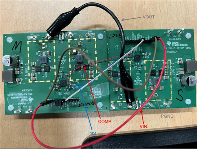
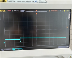
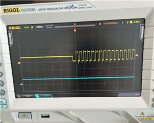
Could you advise how EN1/2 is only 1.2V even when VIN is applied with 12V in LM5143EVM?

I measure VIN and PGND, then see 12V. I measure EN1 and PGND, then see 1.2V. EVM used to work well but out of nowhere its output doesn't come out after several pulse during the startup, and I notice EN pin voltage.There's only 100kohm pull-up resistor on EN pin and I do not see any additional circuitry in the internal block diagram. VCC and VDDA is only ~0.8V. Could you advise?

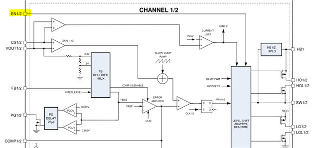
<LM5143 internal block diagram in datasheet>

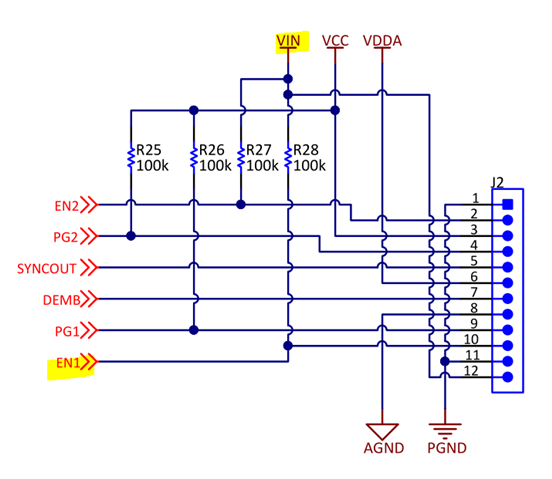
<LM5143EVM schematic>

  • Hi Ella,

    If the EN1 voltage is only 1.2V, there is some leakage current in the 100k pullup resistor. The 100k should actually be sufficient to pull EN1 (and EN2) up to VIN, is there anything connected externally that might cause this pulldown? Internally it's only a comparator with the following thresholds:

    Instead of 2V max, the EN rising threshold is 1.45V min, 1.61V max (avg 1.53V)

    Instead of 0.8V min, the EN falling threshold is 1.04V min, 1.2V max (avg 1.12V)

    Regards,

    Tim

  • Hi Timothy,

    I really have no idea on what is going on.. Please help let me know if you have any idea. Would be highly appreciated!

    - I do sanity check again and confirm that there's no external connection to EN pin.

    - I detach the 100kohm resistor and check that it's really 100 kohm. But ever since I re-attach it, EN voltage becomes 2.2V (previously 1.2V). The output voltage is not generated even though EN voltage exceed the rising threshold.

    - I measure EN pin impedance with 100kohm pull-up resistor detached, and it's almost infinite, which I believe it's normal.

    - Maybe the chip is damaged? Is there any way to check if the chip is damaged or not?

    For the EVM condition, please find the picture below. I configure 4-ph buck using two EVMs. EN voltage of M (Master) is normal, but that of S (Slave) is 2.2V now. 

  • Yes, the IC may be damaged.

    Note VCCX cannot exceed 5.5V. This is connected to VOUT on the EVM, so if you adjust VOUT higher than 5.5V, you need to remove the resistor that connects VOUT to VCCX.

  • What setup are you trying to achieve here? Is this a four-phase design?

  • Note VCCX cannot exceed 5.5V.

    Thanks, it looks the unit is damaged due to the VCCX connection to VOUT (9.5V).

    What setup are you trying to achieve here? Is this a four-phase design?

    Yes, four-phase design. Referring to SLAAE22, I'm trying to change it's output voltage by changing FB voltage. I checked the operation in 2-phase, and try to check 4-ph operation now to see how the response becomes faster.

  • Ok, you need to configure them according to the schematic in the datasheet. SYNCOUT of the first EVM should go to SYNCIN of the second EVM. Also connect MODE, COMP1/2, FB1/2, SS/12 as needed.

  • Thank you for helping me out to find the problem :) 

    May I have one quick question? Cutoff frequency and loop BW that I get from the quickstart are same for 2-ph design or for 4-ph design, i.e. the loop response is solely depending on compensation of 1st phase of master and it's not affected by the number of phase. Please kindly let me know if any misunderstanding here.

  • Are you adjusting the number of phases in the dropdown menu at the top of the quickstart calculator?

  • Yes, I adjust the dropdown menu and check the bode changes. Thank you for pointing that out.

    I replace the slave with a new EVM, but run into a problem to get a proper output, even though the loop is stable per quickstart. Could you please check the quickstart and symptoms?

    LM(2)5143-Q1 quickstart design tool - revB1_SSNWEVM.xlsm

    1. Setting : VIN 12V, VOUT 9.4V 

    When input power supply turns on, VIN drops to 9.5V and Vout is 8.9V. Could you advise why VIN drops? Vout waveform is as below and it makes lots of noise from the board (maybe from MLCC).

    Yellow : VOUT (master)

    Blue : VOUT (slave)

    SW waveform is as below.

    Yellow : SW of 1st phase of Master

    2. Setting : VIN 12V, VOUT 6.75VOUT

     VIN is 12V but VOUT fluctuates a lot between 3~9V and it ends up turning off - switching halts and there's no output voltage. VOUT waveform is as below. 

    Blue : VOUT (master)

    SW node waveform is as below. It repeats halting the switching as below.

    Yellow : SW of 1st phase of Master

    Blue : ignore

    If you have any idea on the error, please help advise.

    + I notice the pictures are not clear in its resolution. Please let me know if you want me to send the high resolution picture thru offline.

  • Hi Ella, 

    I recommend replacing both ICs if VCCX had an overvoltage.

    Note in the quickstart that 0.68uH is too low as the ripple current is 363% (40% is normal). Choose a current limit of 150% of Iout-max and select the sense resistance and inductance accordingly. 20mΩ and 3.3uH is more suitable.

    Four phases for 1.5A seems excessive...the efficiency will be low, especially at 2.2MHz. The transient response is controlled by the loop, not really the number of phases.

    Regards,

    Tim