This thread has been locked.

If you have a related question, please click the "Ask a related question" button in the top right corner. The newly created question will be automatically linked to this question.

BQ25616: Charge Current Variation

Part Number: BQ25616
Other Parts Discussed in Thread: TPS63802

Hi ,

We are using BQ25616 for charging the single Li-ion battery. Along with BQ25616, we are using the TPS63802 Converter for generation of 3.3V.

TPS get input from the Sys node of charger IC. Please see the schematic below,

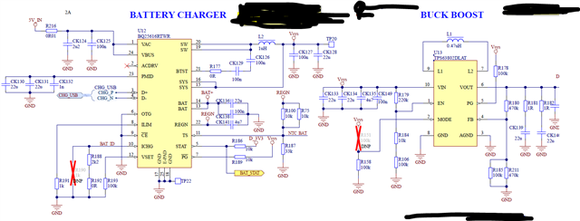
We are using the BB converter in PFM mode. 

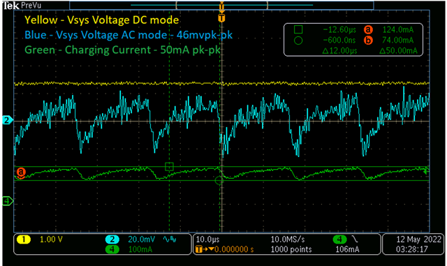
When the device is connected to power source, during the charging of the battery we see variation (instead of DC current, a saw tooth waveform) in the charging current. Please see below waveform

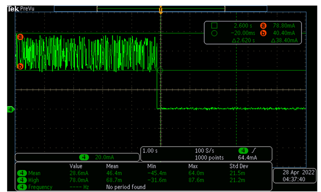
Variation of charging current at termination current range:

Termination current with BB in PFM mode:

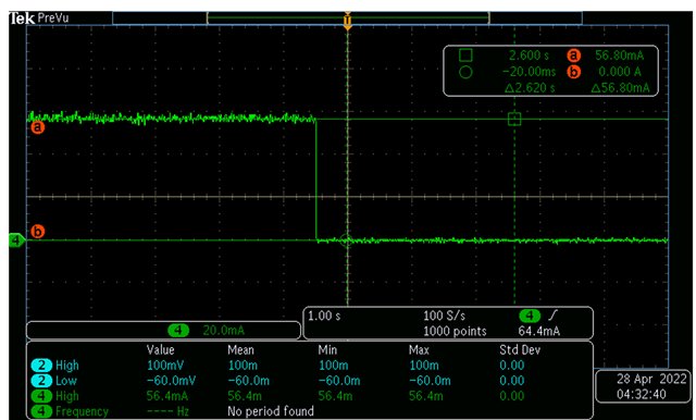
Termination Current with BB in PWM mode:

Our Understanding:

In PFM mode, BB converter switches on/off the converter based on the load. This causes a change in the voltage at the input of BB, which is Vsys. Vsys voltage is used to charge the battery and hence the variation in the charging current. 

Is our understanding correct ?

Questions:

1. Since the Battery current is regulated, why charger IC is not able to maintain constant current ?

2. How does the charger IC detects the termination / pre-charge  current ? current might be toggling above and below the threshold?

3. Is this kind of charging current acceptable for Li-ion batteries ?

4. How can we improve the charging current or make sure the PFM mode does not affect the charging current ?

  • Hi,

    If the BQ25616 charger operates without VSYS load (i.e. BB), how does the charge current behave?

    Thanks,

    Ning.

  • Hi Ning, 

    Without BB or even with BB in PWM mode, charging current is constant. I have attached one ref for charger termination current in the 1st message. 

    Please let me know if you need anymore information.

    Thanks,

    Chandan N

  • Chandan,

    We will work on it the next business day.

    Thanks,

    Ning.

  • Hi Ning,

    Thanks for the update. Looking forward for your support.

    Thanks,

    Chandan N

  • Chandan,

    What does ISYS look like?

    Thank you very much,

    Ning.

  • Hi Ning,

    We could not measure the ISYS as there was no series component to remove.

    Thanks,

    Chandan N

  • Chandan,

    ISYS should also vary. Both SYS and BAT are the output of the charger. When VSYS/ISYS varies all the time, IBAT is also impacted.  The VSYS/ISYS variations need to be minimized.


    Thank you very much,


    Ning.

  • Hi Ning,

    Thanks for the update, even our understanding is same.

    But questions are,

    1. Since the Battery current is regulated, why charger IC is not able to regulate constant current irrespective of variation in Vsys ? 

    2. How does the charger IC detects the termination / pre-charge  current ? current might be toggling above and below the threshold? These is no detailed explanation about the termination current detection mechanism. Is it time based ? how log the current shall be below the threshold ? What if the current goes above threshold in between the time? 

    3. Is this kind of charging current acceptable for Li-ion batteries ? Does TI have any suggestions?

    Thanks,

    Chandan N

  • Chandan,

    1.As mentioned earlier, the charger (a single step-down buck DC-DC converter) supplies the required power to both SYS and BAT. The charger's control loop works to provide adequate current to ISYS (SYS load) and regulate IBAT by adjusting the duty cycle of the buck converter. When the transients on ISYS occur, it takes the closed loop control some time to get IBAT back to steady state.

    2. Proprietary information.

    3. The battery datasheet should specify the charge current allowed.

    Thanks,

    Ning.

  • Hi Ning,

    Thanks for your support and clarification.

    Regarding Point 2.

    • I have tested on 3 boards where Buck Boost configured in PFM mode and the charger IC was able to terminate the charging - full charger detection properly. 
    • We wanted to test the boundary conditions for charger IC to verify that charger IC will not toggle between "Terminating the charging  - full charge"  and restarting the charging due to the variation of the charging current. Since we do not know the implementation, can you please suggest a test method to verify the boundary condition ?
    • Parallelly we are working on to minimize the variation on Vsys.

    Thanks,

    Chandan N

  • Chandan,

    1. The device automatically terminates the charging cycle when the charging current is below the termination threshold, the battery voltage is above the recharge threshold, and the device is not in DPM mode or thermal regulation. When a fully charged battery is discharged below recharge threshold, the device automatically starts a new charging cycle.

    2. Referring to 8.6 Timing Requirements on page 13 of the d/s, the typical deglitch time for charge termination is 30ms, the typical deglitch time for recharge is also 30ms.

    Thanks,

    Ning.