This thread has been locked.

If you have a related question, please click the "Ask a related question" button in the top right corner. The newly created question will be automatically linked to this question.

TPS7A24: No output voltage with the Pspice model

Part Number: TPS7A24

Dear,

I met a problem in the simulation by LTspice.

Short description of the circuit:

There's a current limitation (10mA) after the Voltage Source, the input side of TPS7A24 has 470uF capacitor, the output side has 20uF capacitor.

Problem in the simulation result:

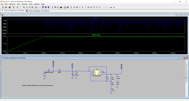
The input voltage was stuck at ~2.1V and cannot rise, so there's no voltage output, it seems there's some kind of current limitation (ilim) in the LDO model, but how can I do with Cout=20uF?

Thanks.

Pls see the screen shot of the simulation below (the blue line is the current through Cout) and the .lib file and the source file which I used.

 tps7a24_trans - Copy.libPower-up-Sequence_12V-LSN.zip

  • Hi Jian,

    Unfortunately due to license restrictions we are unable to troubleshoot modeling issues in LTSpice.  If you want to download our free Cadence for TI and run the simulation in that environment, I can offer additional support if the issue remains - it may be a problem with LTSpice.  If I were looking at this circuit, I would confirm that the voltage going into the LDO (after the diodes) is higher than the enable set voltage.  The diodes may be dropping voltage from Vin and the EN voltage threshold may not be tripped as a result, keeping the device turned off.

    Thanks,

    Stephen