Because of the Thanksgiving holiday in the U.S., TI E2E™ design support forum responses may be delayed from November 25 through December 2. Thank you for your patience.

This thread has been locked.

If you have a related question, please click the "Ask a related question" button in the top right corner. The newly created question will be automatically linked to this question.

TPS628501: Schematic review

Part Number: TPS628501

Dear Team,

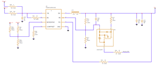
Our customer try to design the circuit for  0.9V and 0.67V dynamically ,  does it have any risk for below design ? thanks.


  1. PMU_SW_CTRL =1 , VCC =(1+13K/(100K//36K))*0.6V=  0.9V
  2. PMU_SW_CTRL =0, VCC= =(1+13K/(100K))*0.6V= 0.678V
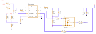
  1. PMU_SW_CTRL =1 , VCC =(1+(42.2K//14K)/(82K))*0.6V=  0.908V
  2. PMU_SW_CTRL =0, VCC= =(1+(42.2K/82K))*0.6V= 0.676V
Many Thanks,

Jimmy

  • Hi Jimmy,

    Thanks for the question.

    Provided that the output is changed with a frequency much smaller than the crossover frequency (therefore it is not interfering with the control loop), I wouldn't expect major problems. Since this is not a standard operating conditions, I would recommend the customer to do proper testing (in particular stability and transient response), to assure that the system is behaving as expected and it meets their specs.

    As general comment, the input capacitor is to small for this IC (I would advise at least 10uF). Please also consider that the effective output capacitance should be > 15 uF across operating conditions.

    Thanks,

    Stefano