This thread has been locked.

If you have a related question, please click the "Ask a related question" button in the top right corner. The newly created question will be automatically linked to this question.

TPS386000: Reset Delay Time Error

Part Number: TPS386000

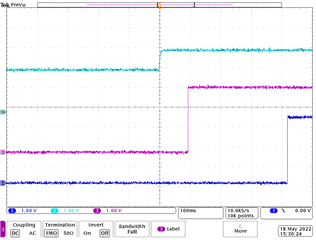
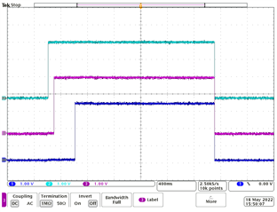
We're using a TPS38600 which monitors 4 different rails, each using a 22 nF capacitor on the Cct pin.  Per the equation pulled from the datasheet, Cct(nF) = [Tdelay(ms) - 0.5(ms)] X 0.242, we would expect a delay time of around 95 ms.. However, we're measuring a delay time between the last rail crossing its threshold and the reset being deasserted (pulled up) to be around 140 ms.  We are using a 100 kohm pull-up resistor (and even tried a 20 kohm pull-up resistor) on the RESET line. The 22 nF capacitor is also ceramic per recommendation of the datasheet to mitigate any leakage. I would expect any stray capacitance on the board to be in the pF range and not be a huge contributor to the almost 50% increase in delay time we're seeing. Is there that much potential error in the calculation vs performance of the reset delay time or maybe I'm missing something else? Thank you

  • Hi Shane,

    Thank you for you question. I will have to double check with our design team for the margin of error for the Tdelay equation. 

    Just to double check, are you able to share the schematic you are using for the TPS386000?

    Jesse 

  • Unfortunately I'm unable to provide a schematic, but I can provide a little more detail about our particular design. The supervisor is running on 3.3V and all four *RESET outputs are wire OR'd together and pulled up using a single 100K resistor. One other thing to note - one of the input rails being monitored is the same 3.3V that the device is running on; perhaps there's a race condition between when the Supervisor starts operating and the 3.3V input crosses its threshold.

  • Is the reset time being measured before or after the OR gate?

    Jesse 

  • It's just a wire OR so no actual gate device. The four outputs are all connected together as a single net.

  • Hi Shane,

    I just double checked your configuration and I am not seeing the delay on my EVM.

    Light blue=sample voltage Pink=CH1 with 22nF and Blue=CH2 with .1uF

    Both CH are showing fairly accurate delay time from the equation. 

    Also monitoring the VDD with one of the CH does not seem to cause a racing condition.

    From the delay that your are seeing, it seems the device is seeing ~34nF.

    How are your CT capacitors connected? Is it directly connected to CT pin and ground?

    Jesse 

  • Thanks for digging in, Jesse. It does seem like our board is operating as if we're using a capacitor around 34 nF. We actually pulled the capacitors from the board and measured them to be 0.022uF as expected. We also measured the parasitic capacitance and it was around 1 nF so that's not significantly contributing to the overall capacitance either. I can confirm that the capacitors are connected between CT and ground and they're very close physically to the supervisor device. Something else to note - we're using two supervisors. Supervisor 1 is monitoring V1, V2, V3, and V4. Supervisor 2 is monitoring V5, V6, V7, and V8. The reset outputs of V1, V2, V3, and V4 on Supervisor 1 are wire OR'd to the reset output of V8 on Supervisor 2. The reset outputs of V5, V6, and V7 are themselves wire OR'd together. SENSE4_H is also grounded on both devices. Both V4 and V8 are connected to SENSE4_L via a voltage divider, similar to all the other voltages being monitored - the dividers just use different resistor values. 

  • Is the extended delay also observe in V5-7 reset output? Also have you tried removing the V8 reset output from the V1-4 reset output?

    Jesse