This thread has been locked.

If you have a related question, please click the "Ask a related question" button in the top right corner. The newly created question will be automatically linked to this question.

LM5122-Q1: Question for LM5122 Dual Phase operation with external clock with frequency spread spectrum feature

Part Number: LM5122-Q1
Other Parts Discussed in Thread: LM5122

Hi Team,

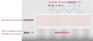
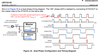
Our customer is using LM5122-Q1 in dual phase configuration, in order to improve EMI performance, they want to check if we can use one external sync clock with spread spectrum feature feed into SYNC pin as below. Can you help to check this design if any issues? Any considerations should be paid attention to?

Thanks.

  • Hi Jacky,

    Thank you for using E2E forums, Regarding your question, yes it is possible to to synchronize the internal oscillator to an external clock using SYNCIN/RT pin. It is mentioned in the datasheet section 7.3.11. Important thing to consider here is that to make sure the frequency of the external synchronization is within +40% and -20% of the internal oscillator frequency that is set by the Rt resistor.

    BR,

    Haroon

  • Hi Haroon,

    Thanks for the reply, we have another question about this operation, as we will modulate the regular input clock with one modulation frequency as explained in below picture, we want to know what's the modulation frequency we can support for LM5122 inside? For example, input external clock is still 250kHz with 50% duty cycle, and modulated with +/-1.4kHz changing in 20ms, can we support this condition?

    Thanks.

  • Hi Jacky,

    I will ask my experienced engineers and get back to you as soon as possible, in two or three working days at the latest.

    BR,

    Haroon

  • Hi Jacky,

    Yes it is possible to support this condition, but for your example in case the external clock is 250 kHz with +/- 1.4 kHz modulation minimum and maximum, your RT internal clock should be adjusted in such a way that the external clock of 250 kHz (251.4 - 248.6 kHz) falls under either +40 % or -20% of the RT internal clock, as you can see in the datasheet in section 7.3.11.

    BR,

    Haroon

  • Hi Haroon,

    We have another question, as you know, for frequency spreading operation, there is one modulation frequency fm as shown in below picture. We want to know what's the limitation for this modulation frequency for LM5122 inside? I'm guessing it should be limited by internal loop bandwidth, but need to know more details about that, please help to check.

    Thanks.

  • Hi Jacky,

    I am a bit confused regarding your question, correct me if I am wrong, you want to externally synchronize the device with a certain modulation frequency that is spread over the triangular waveform as you have shown in the picture. Now what you are asking me what is the range or how wide can this triangular waveform be? Also I am not sure what you mean by the "limited by internal loop bandwidth" could you explain a bit more?

    Could you also kindly tell me the name of the project and customer?

    BR,

    Haroon

  • Hi Haroon,

    Customer is using LM5122 2-phase operation for one 8~36V input, 48V/3A output boost use case for automotive application, but we are facing EMI which is hard to resolve, so we identified this frequency spread method leveraging LM5122's SYNC pin.

    As you know, for triangle frequency spread modulation, there are two factors:

    1. frequency deviation, delta f, which is changing based on central switching frequency set by RT resistors. And now we confirmed as long as within the +40%~-20% range, it is OK for LM5122's spec.

    2. modulation frequency, fm, which is how fast we can change the delta f above. - This is the parameter we want to check what's the range we can allowed for LM5122, can you help to check it?

    Thanks.

  • Hi Jacky,

    I will check with a design engineer and some of my experienced seniors and get back to you.

    BR,

    Haroon

  • Hi Jacky,

    So here is what I was able to get:

    Changing to max frequency is 4x of the modulation frequency, which should be slower than the loop bandwidth, such that the output would not see the modulation ripple and would be in constant transient


    Hence, the modulation frequency should be < 1/4 of the loop bandwidth

    And the speed to transitioning to the max frequency (delta F) is < loop band width.

    Hope this helps.

    BR,

    Haroon