This thread has been locked.

If you have a related question, please click the "Ask a related question" button in the top right corner. The newly created question will be automatically linked to this question.

LM5069: vin voltage drop when LM5069 at low voltage

Part Number: LM5069
Hi team,

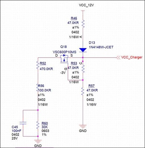
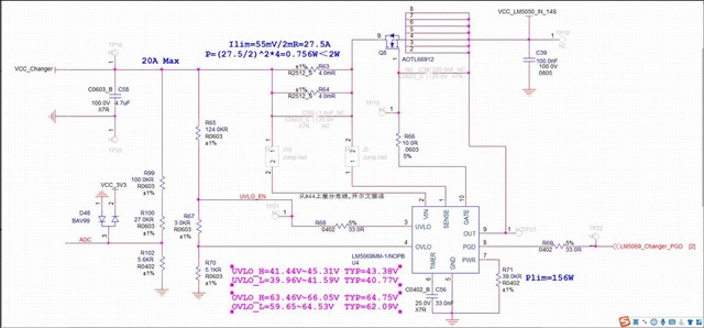
Our customer used LM5069 to design a charge protection circuit consisting of two parts shown below. In their design, the circuit shown in the first picture was used to detected the batteries which they used Vcc_12V to simplify the circuit. If the batteries were detected, the VCC_charger line would connect to 58V voltage source not shown in the picture. And in the second picture there was typical protection circuit based on lm5069,which connected VCC_Charger to the charger circuit.
There was a connecter to connect VCC_Charger shown in the first picture to the VCC_Charger shown in the second picture. According to the resistors shown in the picture, the voltage of VCC_charge was 7.9V((12V-0.7)÷((R53+R57)//(R52+R56+R60)+R46)*(R53+R57)//(R52+R56+R60)=7.9V) without connector. When VCC_Charger in both diagrams was connected ,we can calculate that the voltage of VCC_Charger is 4.9V.
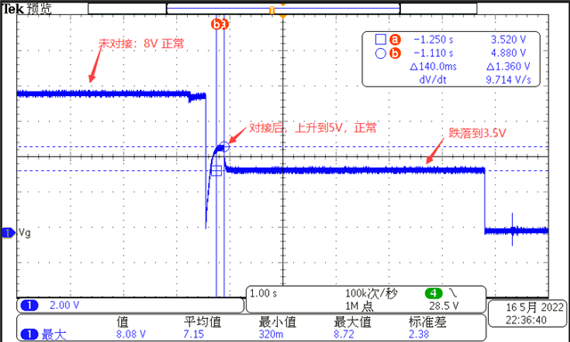
But actually, when VCC_Charger connected in both diagrams ,the voltage of VCC_Charger only maintained at 5V for almost 140ms and then dropped to 3.5V . The wave of entire connection process was shown in the third picture. In addition, when they removed LM5069 and connected VCC_Charger line, the voltage was stable at 5V.
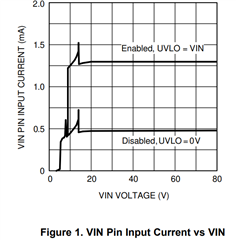
According to the threshold of UVLO and OVLO, LM5069 would not work.
So I want invite you to help to look for the reason why there is s a drop when VCC_Charger is connected with LM5069 on.


Thanks and looking forward to your kind response!

Best Regards,

Nan

  • Hi Nan,

    Can you please include current, Vout and timer voltages in the same test waveform. It looks the device is getting fast triggered during that event.

    Best Regards,

    Rakesh

  • Hi Rakesh,

          Thanks for your kind reply.

          I will invite my customer to do as you told. Could you please tell me more about the fast trigger?

         In addition, according to the resistors, I can calculate that the current which caused the 5V drop to 3.5V is 70uA. Is the current(70uA) the leakage current  of LM5069 at 3.5V or 5V.

  • Hi Nan,

    From your test waveform, the GATE voltage has dropped fast. I meant the device might have triggered circuit breaker event which happens when the current exceeds 110mV/Rsns level.

     In addition, according to the resistors, I can calculate that the current which caused the 5V drop to 3.5V is 70uA. Is the current(70uA) the leakage current  of LM5069 at 3.5V or 5V.

    Sorry, I did not get which resistors you are taking about. Can you elaborate more. LM5069 draws bias current from the OUT pin 

    Best Regards,

    Rakesh

  • Hi Rakesh,

        Thanks for your quick reply.

        Maybe I did not describe questions clearly. Let me make it clear. 

         Actually the customer designed two parts of charger circuit. In the first schematic, we can calculate that the voltage of VCC_Charger is 7.9V ((12-0.7)÷((R53+R57)//(R52+R56+R60)+R46) * [(R53+R57)//(R52+R56+R60)]=7.9V)  

        And then the customer connected VCC_Charger line (shown in the first schematic) to the VCC_Charger line (shown in the first schematic).We can calculate that the voltage of VCC_Charger is 4.9V((12-0.7)÷[(R53+R57)//(R52+R56+R60)//(R99+R100+R102)//(R65+R67+R70)+R46)] * [ (R53+R57)//(R52+R56+R60)//(R99+R100+R102)//(R65+R67+R70)]=4.9V)) 

        And in actual measurement, the VCC_Charger only maintained at 5V for almost 140ms and then dropped to 3.5V(shown in the third picture ). The customer wants to know why the VCC_Charger was not stable at 5V.

       So I have a guess that the leakage current of LM5069 caused VCC_Charger voltage drop. When VCC_Charger reached at 3.5V, we can calculate that the leakage current is 70uA((12-0.7-3.5)/R46) -3.5/(R53+R57)//(R52+R56+R60)//(R99+R100+R102)//(R65+R67+R70)=70uA). So  I want to know my guess is right or not.Is it possible that the LM5069's leakage current is 70 uA  when vin reached at 3.5V? And the customer measured that the leakage current of LM5069 was 100uA while VCC_Charger drop. Is it normal?

       In addition, my customer measure the voltage of timer pin which stay low when Vin drops from 5V to 3.5V.

  • Hi Nan,

    The recommended operating voltage of LM5069 is 9V with rising POR threshold at 7.6V. 

    We don't expect device to draw any current below POR voltage.

    Is VCC_Charger so weak that it cannot support 70uA current ?

    Best Regards,

    Rakesh

  • Hi Rakesh,

        Sorry for delay reply.

        Actually the customer used this as charging circuit switch. But before charging start, they wanted to design a detection circuit to confirm that batteries had been set ready where the 12V was provided by batteries. When batteries got ready, another voltage at 58V would connected into Vcc_Charge.   

        So the problem was that they would measure the Vcc_Charge at 5V via ADC according to the resistors they set in the circuit.But actually the Vcc_Charge was not stable at 5V but 3.5V. So I guess it was leakage of LM5069 that caused voltage drop. So I just want you to help me confirm that whether the voltage drop was caused by leakage or not.  And how much is leakage of the LM5069 when the Vin is low to enable the device?

    Best Regards,

    Nan

  • Hi Nan,

    Understood.

    But unfortunately, we don't have information on the leakage or current consumption of LM5069 when the supply is below POR threshold 7.6V. The device is characterized for Vin>7.6V

    Best Regards,

    Rakesh

  • Hi Rakesh,

       Alright, I would send EVM to customer to measure the leakage current in their application situation.

       Thanks for your reply.

    Best Regards 

    Nan