This thread has been locked.

If you have a related question, please click the "Ask a related question" button in the top right corner. The newly created question will be automatically linked to this question.

TPS6594-Q1: current consumption

Part Number: TPS6594-Q1

Dear team,

If 3.3V Vsys is powered on, and the enable pin is off. What is our device's status? What is the current consumption? 

In my understanding, it should be shutdown current. But in our datasheet, the test conditions of shutdown current is VCCA is powered on which means ENABLE pin is enabled. If the enable pin is disabled, what is the current consumption?

Thanks & Best Regards,

Sherry

  • Hello Sherry,

    The spec item you are referencing is the shutdown current of an individual BUCK, not the entire device. For example, if BUCK1 is disabled you should expect about 1uA flowing into the PVIN_B1 pin.

    If you want to know the current consumption of the entire device in standby and other lower power states you need to refer the current consumption section of the data sheet.

    If 3.3V Vsys is powered on, and the enable pin is off. What is our device's status?

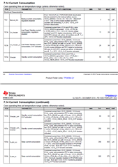
    This will depend on the NVM of device, but in general the PMIC will either be in STANDBY or LP_STANDBY. If you know which features are still on during a particular part number's standby mode, you can use the above table to know the approximate amount of current it will consume.

    -Mike

  • Hi Michael,

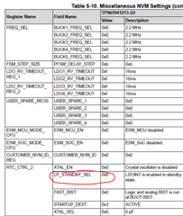
    1. In my understanding, this depends on the configuration of LP_STANDBY_SEL, right? If LP_STANDBY_SEL=1, then it should be LP standby mode. For TPS65941213-Q1, could you please tell me what the configuration is?

    This will depend on the NVM of device, but in general the PMIC will either be in STANDBY or LP_STANDBY.

    2. In below picture, both Standby mode and LP Standby mode requires VIO=0 while my customer connect VIO to VCCA, so VIO is also 3.3V. Then what is the consumption current?

    3. In my old understanding, ENABLE pin controls all analog and digital circuit, so if enable pin is disabled, 6594 won't work with VCCA=0V. But the fact is VCCA is still 3.3V even though ENABLE pin is disabled. So I want to know what does ENABLE pin control? If ENABLE pin is disabled, which part is disabled?

    Thanks & Best Regards,

    Sherry

  • 1. In my understanding, this depends on the configuration of LP_STANDBY_SEL, right? If LP_STANDBY_SEL=1, then it should be LP standby mode. For TPS65941213-Q1, could you please tell me what the configuration is?

    For the details of a specific part number, please refer to the corresponding user guide. For the TPS65941213 in PDN-0C it is found here.

    3. In my old understanding, ENABLE pin controls all analog and digital circuit, so if enable pin is disabled, 6594 won't work with VCCA=0V. But the fact is VCCA is still 3.3V even though ENABLE pin is disabled. So I want to know what does ENABLE pin control? If ENABLE pin is disabled, which part is disabled?

    The ENABLE pin does NOT control all analog and digital circuits. The safety circuit that controls the switch between VSYS and VCCA is not impacted by ENABLE pin.

    The ENABLE pin acts a trigger for state machine of the PMIC or PMIC pair. In general setting ENABLE high, the PMIC will attempt to enter the ACTIVE state unless a higher priority trigger is set. If ENABLE goes low, the PMIC will enter a lower power state (STANDBY or LP_STANDBY usually) where most if not all the rails are disabled. Please refer to PDN user guide to understand which rails are enabled/disabled in different power states.

    I need to get back to you about your question 2.

  • Hi Sherry,

    Sorry about the delay. Mike should be able to get back to you on Tuesday, today is public holiday in US.

    Thanks.

    Regards,

    Tomi Koskela

  • Sherry,

    I've reached out to our testing team for support on question 2. I hope to get an answer soon.

    Regards,

    Mike