This thread has been locked.

If you have a related question, please click the "Ask a related question" button in the top right corner. The newly created question will be automatically linked to this question.

BQ25792EVM: About Quiescent battery current in VBUS connected condition

Part Number: BQ25792EVM
Other Parts Discussed in Thread: BQ25792

Hi,

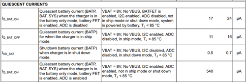
Could you tell me about quiescent battery current in VBUS connected condition?
Customer is using EVM to measure Iq.

In the case of ”VBUS=0V , VBAT=4.86V , Charging stopped state” condition, it was 17 μA.
This matches the data sheet specs.

However, in the case of ”VBUS=5.14V ,VBAT=4.86V, Charging stopped state” condition, quiescent battery current increased.
The actual measurement is about 380 μA.

Could you tell me why quiescent battery current increases with VBUS connected?
And Please advise how to make  smaller with VBUS connected.


Regards,
Yusuke

  • Hi Yusuke,

    Forcing HiZ mode, either with the ILIM_HIZ pin or with the HiZ bit, results in the switching FETs turning off, V(SYS)=V(BAT) and lowest Iq.

    Regards,

    Jeff

  • Hi Jeff,

    Thank you for your support.
    Customer is able to reduce quiescent battery current by using Hi-Z status.

    Let me ask you two questions about the operation of BQ25792 without Hi-Z.

    1.Could you tell me why quiescent battery current increased despite the existence of VBUS?
      Customer expected to switching FET drive sourced from VBUS.

    2.What are the criteria for deciding whether to use the VBUS or Battery source as the drive power source for the BQ25792?


    Regards,
    Yusuke


  • Hi Yusuke,

    Regarding 1, the converter still needs to switch in order to regulate SYS voltage.  Also, there will be refresh pulses to keep the BTST caps charged.

    Regarding 2, if VBUS has a power source attached and HiZ is not enabled, VBUS powers the IC.  If VBUS has no power source attached or HiZ is enabled, the battery powers the IC.

    Regards,

    Jeff

  • Hi Jeff,

    Thank you for your response.
    Please excuse my lack of explanation about Regarding 1.

    >Also, there will be refresh pulses to keep the BTST caps charged.
    I don't know the connection between the above and the increase in battery current consumption.
    How is battery voltage used for converter operation?
    Could you explain that to me in a little more detail?


    Regards,
    Yusuke

  • Hi Yusuke,

    The battery voltage is not used to power the converter, only power from VBUS.  Even if charging has stopped, the switching converter must switch occasionally in PFM or constantly if PFM is disabled in order maintain SYS voltage regulation slightly above the battery voltage. 

    Regards,

    Jeff  

  • Hi Jeff

    Thank you for your explanation.
    I got three additional questions from a customer.
    Could you give me your opinion?

    ・I understand that when the converter is running, there will be a leak current from VBAT depending on VSYS.
     Could you tell me the VSYS condition where the leak occurs from the BAT voltage?
        If it is PFM operation, the VSYS> VBAT state will continue. Please tell me the theory of leaks from VBAT.

    ・Is there any  battery current consumption information or electrical characteristics when VBUS is connected?
     
    ・When Hi-Z mode is enabled, OVP and OCP are disabled. Is this understanding correct?

    Regards,
    Yusuke

  • Hi Yusuke,

    When VBUS is applied and the converter is running in forward/charge mode but charge is disabled, there should be very little current flowing from battery into BAT and BATP pins.  We don't characterize battery leakage current when VBUS is connected.  If your customer is seeing large current then the IC is damaged.

    Regarding OVP and OCP being disabled in HiZ mode, OVP is disabled but OCP for discharge current out from BAT to SYS through the BATFET is enabled.

    Regards,

    Jeff