This thread has been locked.

If you have a related question, please click the "Ask a related question" button in the top right corner. The newly created question will be automatically linked to this question.

TPS3806I33-Q1: input pin Injection current

Part Number: TPS3806I33-Q1

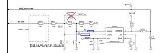
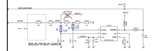
Will you please confirm if the following circuit is violating any of the ratings in the datasheet.

If yes, please help to provide any calculations on priority.

 Also in case input / KL30F line may have +/- 150 volts for 50 msec or 5 seconds, which specifications will get violated if any.

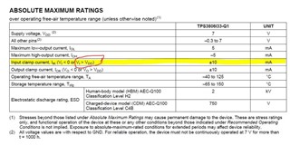
We understand injection current for Vin > VDD is +/- 10 mA.


  • Hi Dnyanesh,

    With the current resistor values and if KL30F provides 150V the VLSENSE = 150V * (5.6K + 69K + 1K)/(4.7K + 220K + 5.6K + 69K + 1K) = 35.6V which is way above the pin tolerance of 7V. What is the nominal Voltage on this line?

    Also, it is recommended that the total of the resistor values for the voltage divider on the HSENSE and LSENSE to be roughly around 1Mohm. This is advised to prevent current leak from the battery. 

    Jesse 

  • Thanks a lot Jesse for replay. Now agreeing ,VLSENSE =  35.6V, as you have calculated above, can we add series resistor R1 / R2 (for other line) to limit the injection current < +/- 10mA  (Vin > VDD) as shown below? so in this case even if VLSENSE =  35.6V, will it damage the IC if we choose R1 and R2 to limit the current to 50% than given in the datasheet, for example 8.2k.

    normal voltage on that line will be 8 to 18 volts.

  • one more idea, or the position of R3 and R4 is better since it will form RC filter as well, apart from limiting the clamp/injection current !  :)

  • Hi Dnyanesh,

    Unfortunately, damping the current would not prevent the damage from the over voltage. I would suggest putting a 25V voltage clamp on the KL30F line should do the trick.

    Jesse 

  • Thank you Jesse. please help to understand on the specifications given in the datasheet for injection current in details. this is contradictory to above statement that even damping the current below specification's will damage from the over voltage. what is validation method for this clamp current from TI side. In case we want to validate this what are recommended tests / set-ups ? condition clearly says Vi > VDD  is acceptable. 


  • Hi Dnyanesh, 

    I will have to check with the dev/validation team on the clamp current mechanism. I will update you once I get info.

    Jesse  

  • No problem to wait Jesse, however lets understand clamp current mechanism in detail with any dev/validation reports. Thank you. 

  • Hi Dnyanesh,

    The input/output clamp current is the maximum current that can pass through the ESD of the device. 

    Jesse 

  • Since now we are talking about ESD, this levels are 4KV for HBM and close to 750Volts for CDM. Does this mean we can add 4 Mohm and 750K series resistor to pin to limit the current below 10mA respectively, in order not to damage the device ? assuming we dont want to use the ESD capacitors. 

    Its better to have a call.  when can we set up call with Dev/Validation team ? 

  • Hi Dnaynesh,

    For the maximum rating of the device, the voltage and current rating are viewed as independent from one another and the device should not be operated with a violation on voltage and/or current  spec. As for the ESD, it is a safety, used to protect the device from environmental anomalies and should no be the basis for the application parameter. 

    Jesse  

  • I totally agree Jesse. this should not be considered as normal operating situation. Normally on this line, as mentioned above voltage will not exceed battery line voltage i.e. 16 volts. only in case of environmental anomalies that can go upto 70 volts for 200 msec worst case as per specs given by OEM. In validation test, this test is for only 1 pulse. we have made set-up where we have given 80volts/200msec , 2000 pulses and no issues found !!!  :)  of course injection current was limited to 1mA. 

    what about following reports ?

    No problem to wait Jesse, however lets understand clamp current mechanism in detail with any dev/validation reports. 

    Warm regards...