This thread has been locked.

If you have a related question, please click the "Ask a related question" button in the top right corner. The newly created question will be automatically linked to this question.

LM27762: Schematic vs Demo, problems getting proper voltage output

Genius 13959 points
Part Number: LM27762

Hi Experts,

Good day. Seeking help on this query:

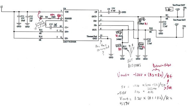
See below circuit, built to get +5/-5V output. The resistor values in squares are from the evaluation board.

Not sure of the Pgood resistor has to be connected for a correct output. I am only getting 1.2V output.

Thank you for your support.

Regards,
Archie A.

  • Hi Archie,

    The schematic looks fine.

    1. Could you share the layout with us?

    2. Do you observe the same problem on multiple boards?

    3. Is the IC already damaged? Have you tried to swap the unit? 

    4. Could you share Vin, +Vout, -Vout, Ccp, Cfly waveforms?

    5.What is the max load on both rails?

    6. You can also order the EVM for this device to get a known working circuit to test out.

    7. Could you share the part numbers of the capacitors?

    Regards,

    Febin

  • Hello Febin,

    Sorry for the late update as my Cx just returned back with us. Below is their response.

    We have been taken off this project, but will be back on it shortly. Questions: Does Pgood have to be connected for the circuit to work? Also, since only getting 1.2V, instead of 12V, is it possible theres something off by a factor of 10?

    Thank you.

    Regards,
    Archie A.

  • Hi Archie,

    PGOOD is an open drain output pin. Connect to ground if not used. 

    12V is a wrong reading... The PGOOD is tied to Vin and I would expect a voltage within this range...

    I just noticed that at the output of LM27762, you have written 12V. Infact the design is for +5/-5V output. Why is it so?

    Regards,

    Febin

  • Hello Febin,

    Thanks for the info.

    We realized it is a 5V+/5V- design after, but could use if we indeed got 5V, but only getting 1.2V, so what does your comment, "The PGOOD is tied to Vin and I would expect a voltage within this range" mean? 1.2V, 5V, 12V. Are you saying you must connect PGOOD to ground or Vin to get any output voltage?

    Regards,
    Archie A.

  • Hi Archie,

    Please allow me to jump in since Febin is out of office.

    Thanks a lot for the update.

    The device can indeed only provide outputs between ±1.5 V and ±5 V. In your case it should be ±5 V.

    Regarding your problem, are you reading a ±1.2 V on both outputs?

     Could you please measure the voltage at the following pins and let us know?

    - VIN

    - CP

    - OUT+, OUT-

    - FB+, FB-

    - PGOOD

    Regarding the PGOOD pin, I would recommend to connect it either to VIN (with pullup resistors) or to GND, as specified in the datasheet, to avoid possible interference. In this case, the PGOOD voltage should be either VIN or GND.

    Thanks,

    Stefano

  • Thanks, Stefano, for supporting this query.

    Here are the voltages on the pins reported by Cx:
    VIN= 5.01V
    CP= -1.1V
    OUT+ = 1.15V
    OUT- = -1.30V
    FB+ = 1.14V
    FB- = -1.69V
    PGOOD (pulled high)= 1.8V to 2.2V (wave)
    PGOOD (pulled low), OUT +/- doesn't change
    The schematic was based on the attached TI reference (look at project title).

    For your further assistance. Thank you.

    Regards,
    Archie A.

  • Hi Archie,

    Thanks for your reply.

    There are my concerns:

    - ideally, CP has to be equal to -VIN, If this does not happen, I would suspect that one of the following things is happening; either an overcurrent on the output (I would advise to remove R5 and R10 if not already done), or the device as been damaged / bad soldering to PCB. Has the device ever worked in the customer application?

    - the pin FB+ and FB- should be high impedance pins, therefore the difference between FB and VOUT should be only determined by the feedback resistor dividers. If this does not happen, I would check the soldering of the resistors and eventually replace them. In particular, I am not sure how FB- could be higher (in absolute value) than VOUT-.  

    In general, have they ever tried to replace the IC to check whether the component has been damaged?

    Thanks,

    Stefano

  • Hi Archie,

    Do you need further support on this issue? If not, I will go ahead and close this thread.

    Regards,

    Febin

  • Hello Febin/Stefano,

    Thanks for pushing this post.

    Still waiting with the Cx confirmation. Will close this case once he confirmed.

    Thank you very much.

    Regards,
    Archie A.

  • Hi Archie,

    Please update us when you hear back from the Cx.

    Regards,

    Febin