This thread has been locked.

If you have a related question, please click the "Ask a related question" button in the top right corner. The newly created question will be automatically linked to this question.

TLV62568: Boost trick

Part Number: TLV62568
Other Parts Discussed in Thread: ISO1042,

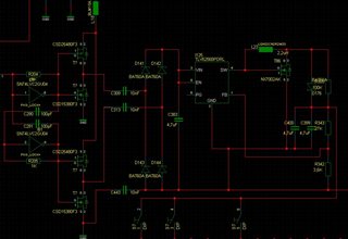
Lacking a cheap, fast boost controller I am considering a trick to use this device as a simple boost converter from ca. 4V to 5V.

The design is as follows:
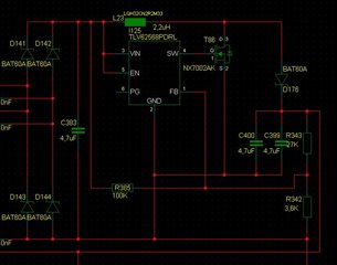
 

Can this work?

My main concern is the start-up or a temporary output short-circuit where the device might go into 100%-PWM and not recover. I try to prevent that with the resistor from the input to the voltage divider, but the behavior for the LDO-function isn't well specified.

Any other suggestions?

  • Hello,

    The device is optimized for a step-down operation. We do not recommend to use it outside of datasheet recommendations.

    Thanks!

    Best regards

    Sneha 

  • As a development engineer I have to strongly disagree. Creative, unexpected use of components is the liveblood of innovation and is actually routine as e.g. researched under the title of lead-user analysis. I did not ask for a recommendation. If you so will I asked for a state-of-the-art boost controller that I cannot find. Therefore my plan B. I use stuff outside the intended application of the vendor every day, it is a key secret for success. I do not care what the vendor thinks, I care what the customer thinks of my result. I cannot find any risk for this controller in the way I use it, it is actually a boring function to carry out for him. However, the supervisions integrated for the buck function are not active in the boost use. So I have to understand some cornercases better. This is what the request is about. The dropout function is not well specified in the datasheet. I do like good datasheets. This should be about clear engineering arguments, not cautious hints.

  • Hi Alfred,

    The device was characterized for all the corner cases for which it is defined in the datasheet. Outside of those specs, we cannot determine the device's performance.  Even if the customer would like to use it outside of defined specs, it is the customer's responsibility to confirm its stability, reliability and performance. I will not be able to help you for any field return/customer problem outside of those already defined for the device.

    Thanks!

    Best regards

    Sneha 

  • As I see it I do not use it outside any of its specifications. The specific point that is unclear to me is chapter 7.3.2 in the datasheet, the (somewhat unusual) dropout mode. This is a nice feature, but I do not see the characterisation under which conditions the 100% duty-cycle operation would be entered. As far as I can see this is the only information I woud need. Probably it would only be entered if Vin is around the set Vout, but that range is in principle arbitrary. Also it can be entered if the load is heavy and it is unclear when that would be the case. 

    In short: the question is about the specification of the 100%-regime.

  • Hi Alfred,

    Please let me give you a feedback tomorrow. 

    Best regards

    Sneha 

  • 1. First I should explain what it is for: We intend to do a capacitively isolated supply for a CAN interface such as the ISO1042, which is a high-volume usage scenario. We need around 100mA @ 5V. There are products for that, of course, but we think we can come out with a better cost strucure. Sorry for the competition, but that's life.

    2. After exploring a dozen circuit variants we think the one with a secondary boost regulator is promising. Unfortunately the cheap MC33063 is slow and looks dated. Therefore the search for an alternative that allows to reduce the size of the inductor.

    3. The concern about the buck converter going into 100% mode and shorting the rail is less bad than it looks. Due to the use-case the Vin-supply is comparatively high impedance and the regulator would go into UVLO and recover. Possible, but not elegant.

    4. But there could be a better topology: As the regulator's SW-node can drive current, I can draw it from there instead of the rail. Then the internal current sensing would detect an overcurrent. From the regulator's point ov view everything looks like a standard buck situation, only the far side of the L is connected differently, what should not matter. The resistor across the boost diode below shall mimic to the SW-node the situation when its drivers are off.

    Here a better screenshot:

    (Instead of the discrete FETs on the left I'd like to have two power stages in an SOT-666, but well...)

    5. If I were a product manager I'd seriously discuss this sales-boosting idea in an application node (if it is not fatally wrong).

  • Hi Alfred,

     When operating in 100% mode (high side FET is turned on always), there will be a voltage drop across the RDS(on) of this FET and the DCR of the inductor. So your output will always be lower than your input by an amount that depends on the load current.

    You can use the equation provided in section 7.3.2 to calculate the minimum voltage required for this mode of operation. 

    You can also refer to this app note to understand the100% mode operation in converters. 

    https://www.ti.com/lit/pdf/slyt747#:~:text=The%20100%25%20mode%20minimizes%20this,of%20the%20high%2Dside%20MOSFET.

    Thanks!

    Best regards

    Sneha 

  • That's fine, but the output voltage is determined after the diode (D176). With the FET at the SW-node (T86) it becomes a boost converter.

  • Hi Alfred,

    As I mentioned earlier, I will not be able to evaluate the device performance in a boost application. Please verify the device behaviour on your implementation by analysing the stability, transient behaviour and all other important parameters. 

    Also, please look into the boost portfolio from TI. You might find a simple and fast boost converter with a similar cost structure as TLV62568.

    https://www.ti.com/power-management/non-isolated-dc-dc-switching-regulators/step-up-boost/overview.html

    Thanks!

    Best regards

    Sneha

  • Indeed there is the TPS613222A with a suitable cost; I missed that one.

    Regarding the buck, nevertheless, the application note explains what it does and why it is there, but not how it is done.

    The question boils down to which information the controller uses:

    a. Feedback only (unlikely)

    b. Feedback and input voltage (but how to know the voltage divider ratio?)

    c. Also the voltage at the switching node under certain circumstances. (There is something in the block diagram, but it is unclear.)

    It remains a mystery for me under which precise conditions the 100% duty-cycle mode is entered.