This thread has been locked.

If you have a related question, please click the "Ask a related question" button in the top right corner. The newly created question will be automatically linked to this question.

BQ20Z90: Flashing DFI data over SMBUS to fuel gauge

Part Number: BQ20Z90
Other Parts Discussed in Thread: BQ29330, BQSTUDIO

Hello TI,

We are working with BQ20Z90+BQ29330 for our end product where two Thermistor voltage input is required to read temperature from two battey packs located at seperate locations.

Now we need to flash DFI image to BQ20Z90 from Host Device, in our case a processor running linux kernel 4.19.

So we are looking for C source implementation, we found only VB6 code for Reading and Writing Dataflash.

Now by following document "SLUA379E" we are able to make our logic for reading but not sure if that is correct or not.

As we found that peoples are facing issues of damaging fuelgauge while writing DFI file using VB6 code.

So we just first trying to Read flash and after that we will try to write dataflash.

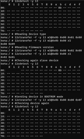
As we just only tried to read the BQ20Z90 with below logic and BQ20Z90 fg got corrupted and we are only getting Slave device address as 0x0b

Hopefully we are able to recover the BQ20Z90 via "TI bq Gas Gauge Evaluation Software "

Here is our logic that we  are using.

Using below code inside kernel module because by using userspace application for smbus device, it is not responding in Unsealed and fullaccess mode as well.

There are ROM commands 0x09 and 0xC0 is used, do you have any document where we get details for ROM commands. it looks like just a magic number without any details.

=======================================================

char *gauge_flash_read(void *pHandle, char *pFS)
{
TI2C *tmpHandle = (TI2C *)pHandle;
int iNumberOfRows;
long lError;
int iRow;
int iIndex;
int iLen=32;
//int iFileNumber;
unsigned char yRowData[32] = {0};
unsigned char yDataFlashImage[0x700] = {0};

// FOR CLARITY, WITHOUT USING CONSTANTS
// 0x700 is the data flash size.
iNumberOfRows = 0x700 / 32;

// PUT DEVICE INTO ROM MODE
// lError = WriteSMBusInteger(0x0, 0xF00);
lError = gauge_cmd_write(pHandle,0x00, BOOTROM);
udelay(90);
// DoDelay(0.01);


// READ THE DATA FLASH, ROW BY ROW
   for (iRow = 0; iRow <= iNumberOfRows - 1; iRow++)
   {
          // Set the address for the row. &H9 (0x09) is the ROM mode command.
          // 0x200 is the row number where data flash starts.
          // Multiplication by 32 gives us the actual physical address where each row starts
         // lError = WriteSMBusInteger(0x9, (0x200 + iRow) * 32);
          lError = gauge_cmd_write(tmpHandle,0x09, (0x200 + iRow) * 32);
         udelay(90);
         // Read the row. &HC (0x0c) is the ROM mode command.
         // lError = ReadSMBusByteArray(&H, yRowData, iLen);
         lError = gauge_read(tmpHandle,0x0C, yRowData, iLen);
         udelay(90);


                         //Copy this row into its place in a big byte array
                         for (iIndex = 0; iIndex <= 32 - 1; iIndex++){
                         yDataFlashImage[(iRow * 32) + iIndex] = yRowData[iIndex];
                         printk(KERN_ALERT "0x%02x, ",iIndex,yRowData[iIndex]);
       }
}
// // WRITE DATA FLASH IMAGE TO FILE
// iFileNumber = FileSystem.FreeFile;
// Open(sFileName); // // Put #iFileNumber, , yDataFlashImage
// Close(); // // EXECUTE GAS GAUGE PROGRAM
// lError = WriteSMBusCommand(0x8);
// lError = gauge_cmd_write(pHandle,0x00, BOOTROM);
pFS = yDataFlashImage;
lError = gauge_control(tmpHandle, 0x08);
//udelay(90);
return pFS;
}
EXPORT_SYMBOL(gauge_flash_read);

=====================================================================

Thanks

Girish

  • Hello Girish,

    TI provides https://www.ti.com/tool/BQMTESTER to program the DFI image (Stored as ROM file). We are unable to review code because each system has different implementation and there are too many variables that can impact actual communication on the bus.

    I would recommend that you do all  the steps from Pro screen of bq Evaluation software. Once you are successful there, then check if your code implements the exact same commands.

  • Hello Shrish,

    Thanks for direction, yes after using Pro screen I get confidence to understand how data flash is programmed.

    Now I am in a very rare situation where I am not sure if this issue is still exist or only I am facing.

    I implement the same code.

    I am using SMBUS calls to read and write data.

    Everything works fine like I can write on MAC and read 2 bytes and I have correct values.

    But when I am initializing BOOTROM mode for Data flashing just after UNSEAL.

    The Slave device just get disappeared from I2C bus. Means there is no slave device showing on SMBUS lines.

    So after sending device into BOOTROM mode device got disappeared and I am not able to flash any data.

    To recover bq20z90 slave device on SMBUS I have to kick start the EVM by disconnecting and connecting power to PACK+ and PACK-

    Now every thing is implemented in code except that device just got disconnected after sending BOOTROM command 0x0F00 to MAC 0x00

    Do you have any idea about this issue.

    Thanks

    Girish

  • Hello Girish,

    You may be seeing the Dashboard of bqStudio showing no slave device. This is expected. You should turn the dashboard Refresh OFF when using Advanced Comm to prevent interference.

  • Hello Shirish,

    This is confirmed from my side that device is unable to boot in BOOTROM mode.

    May be during testing via Pro screen I just accidently erase Rom code.

    So device always visible at 0x0b address in Gas Gauge mode when ever I try to send it in Bootrom mode it get disconnected.

    I checked with bqEval Sw and i2c commands, in both case this is happening.

    So is there any chance that I can flash .senc file to BQ device without sending it in ROM mode?

    Please let me know if any document help me on this.

    Please have a look

    Thanks

    Girish

  • Hello Girish,

    The command may not be supported in BOOTROM mode. Try a read word with command 0x0D

  • Hi Shirish,

    As you suggested

    I tried on UI

    Write successfull

    After that reading 0x0D

    Error message

    Thanks

    Girish

  • Hello Girish,

    That is not normal. It could be something with your circuit. Can you check that the bq20z90 is powered when it is not responding?

    I would recommend that you try on the bq20z90 EVM to rule out other factors.