This thread has been locked.

If you have a related question, please click the "Ask a related question" button in the top right corner. The newly created question will be automatically linked to this question.

UCC28070: Variable PFC Output Voltage

Part Number: UCC28070
Other Parts Discussed in Thread: UCC28180, UCC28019A

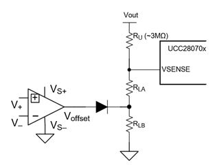
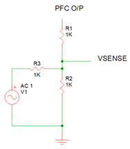
In my current design, the output voltage needs to be adjustable. To do this, the resistor divider for the VSENSE will have its bottom resistor connected to a variable voltage source instead of GND. When this voltage source is zero, the output voltage will be maximum. The resistor dividers for VSENSE and VINAC will be made identical as usual and the normal setup will be valid when the voltage source is zero. As far as I can see, the reason that these resistor dividers are made equal is for the current synthesizer. When the added voltage source is not zero, the current synthesizer will not work properly. However, I will not be using the current synthesizer, and I don't see any reason that this modified arrangement will cause any problems. Is there any other function inside the UCC28070 that would be thrown off by this arrangement?

  • Hi John,

    I'm assuming you're going to disable the synthesizer (by connecting RSYNTH to VREF) and supply the CSx signals externally.

    I have no experience with using a variable voltage source at the bottom of the output voltage resistor string to adjust the output voltage, but here are a few things that jump out to me:

    - Since the impact of output ripple is higher at low Vout than for high Vout, you'll want to size your output caps and boost inductor based highest transient current at the lowest Vout to avoid unintended OVP

    - While you're adjusting the voltage seen on VSENSE, the OVP and SS are based on fixed voltages (~3V and ~0.7V, resp). You need to make sure you keep these thresholds in mind.

    - Ideally, you want your voltage source to be able to sink current all the way down to zero volts, otherwise, you're going to get voltage offset on your output when it cannot sink enough current to regulate and normally, and ultimately, will result in the bottom resistor being removed from the circuit. You need to consider how this will impact your system.

    - Consider what happens if your offset voltage source fails; the PFC will ultimately trip OVP, but you'll need to make sure the output voltage in that case doesn't take out downstream circuitry.

    - Consider breaking up the lower resistor on on the output string so that you always have a divider on VSENSE to avoid the above conditions when your supply isn't behaving as an ideal source or is disabled completely. Perhaps something like this:

    That's about all I can come up with right now.

    Regards,

    Ray

  • Hi Ray,

    Thank you for the points you raised. After thinking about what you said, this is a much better way to vary the output voltage.

  • Ignore the resistor values and the voltage source saying "AC" because it is variable DC (I illustrated using SIMetrix). This way there is always a resistor to circuit common. R3 and V1 could also be replaced with a current source.

    I presume from you answer that if I don't use the current synthesizer (and disable it), no other problems will arise for the internal workings of the UCC28070 if the two resistor dividers are different.

    I have had discussions with my team whether to make this an interleaved or non-interleaved design. There seems to be no efficiency advantage to interleaved after doing loss calculations including switching losses. The main advantage of interleaved is that it halves the high frequency ripple on the input and output and it spreads out the losses and enables a smaller input filter. Anyway, I am planning to use just one channel of the UCC28070. I have done that before for testing and I don't see any problems. Please let me know if I am missing something.

    In the UCC28070, is the 3V reference for the VSENSE error amplifier derived from the 6V VREF? In other words, does the 3V reference track with variations in the 6V reference?

    Thank you.

  • Hi John,

    If you disable the synthesizer, the two resistor dividers can be different.

    I will need to verify that 3V is produced by a divider from Vref and will therefore track and is not a separate regulator.

    Another benefit of dual phase is to reduce the output ripple and allow for smaller power components on the output, including inductors. This may lead to a more efficient layout depending on your design goals.

    If your power level doesn't require both phases and you don't benefit from the synthesizer, you may also want to consider the UCC28180 CCM PFC www.ti.com/.../ucc28180

  • Hi Ray,

    When you say "including inductors" are you referring to the boost inductors or additional output filter inductors? In my application high frequency output ripple is not critical.

    Do any of you know from experience how much the interleaved topology reduces the input filter size since the ripple is cut in half?

    How does the UCC28180 extract the input voltage information to do PFC when it doesn't directly sense it? Who came up with the idea behind it?

    Thank you.

  • Hi John,

    Yes, for a two phase output, the boost inductors, diodes and the boost MOSFETs can be sized for half the total output current than would be required for a single phase solution. If that's not important, then I wanted to make you aware of a few other options.  The UCC28180 and UCC28019A are popular single-phase PFC for sub-3kW designs.

    Correction to my original answer regarding input filter effects of interleaving: The input filter components can be reduced in proportion to the ripple reduction in going from single phase to dual phase. Note that the dual-phase ripple frequency will be twice the single-phase ripple frequency, so the filter cut-off frequency would need to be adjusted accordingly.

    Here's a good description of how the UCC28180 determines Vinac without sensing it directly : https://e2e.ti.com/blogs_/b/powerhouse/posts/is-pfc-possible-without-input-voltage-sensing. I'm not sure who did this first, but most (or all) power electronics suppliers have an average current mode control PFC.

    Regards,

    Ray

  • Hi John,

    I owed you info on the 3V reference. It is a divider off of VREF.

    Regards,

    Ray

  • Thank you very much Ray. Best regards, John Fletcher