Other Parts Discussed in Thread: LM5020,
My design uses an LM5020 boost converter to step up 48 V to 67 V. This passes to a TPS2492PW which serves to limit power and current to the load, as the load is subject to short circuits under certain fault conditions.
In test, it became apparent that the TPS2492 was tripping off power to the load under less than the designed current, power and time limits.
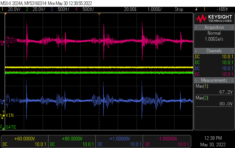
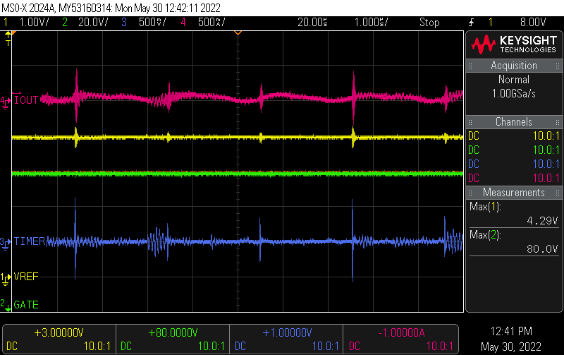
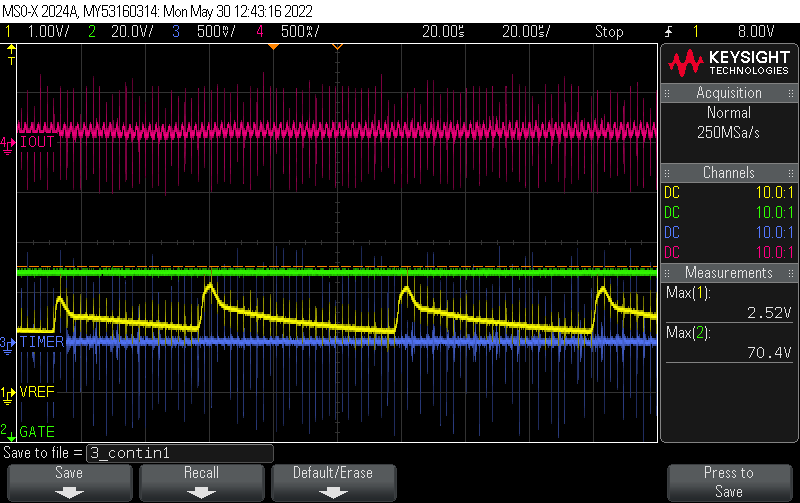
In short, I found that at light load currents, the boost converter is in discontinuous mode and all pins on the TPS2492 probe as you'd expect. As load current increases to and passes the threshold into continuous mode, Vref (Pin 2) which should be at 4 V, at first begins to oscillate between about 4 V and 1 V, and finally settles at 1 V as the boost converter gets fully into continuous mode. I assume it is this disturbance in Vref that would explain why trip thresholds are not what they should be.
Disabling the boost converter fixes the problem, trip thresholds are as designed. Using an external 67 V power supply in place of the boost converter fixes the problem, trip thresholds are as designed.
The operation of the boost converter otherwise appears normal to me at all times, there is no big change in the noise on the output, or observations on other circuit nodes, as it switches conduction modes (other than seeing it change modes). There is no change I can see on the pins probing the TPS2492, except the problem with Vref. I tried adding 1 nF per datasheet Vref to GND, no difference. With boost disabled, I tried probing pins of the TPS2492 with an RF injection probe sweeping from 50 K to a few MHz to see if I could trigger the same behaviour. I could get some feedthrough of the injected frequency to Vref by using high (10 V +) signals on the function generator, but not the same snap to 1 V behaviour.
Any ideas?