Other Parts Discussed in Thread: LM74720-Q1
Hi,
We have an application that need to isolate a circuit with motors from the power supply of a whole system consisting of many electronic boards. The power supply of the system is 36V.
The LM74722-Q1 seemed to be the proper device to act as an ideal diode and to be able to protect the power supply and the other circuit from the back electromotive force when the motors decelerate.
The output of the supply going to the motors has a large capacitance (2200uF) and the individual motor drive boards have themselves large capacitors.
We have a circuit to choke the motors back electromotive force re-injected in the supply.
We had a problem just powering the whole system and disabling the enable pin of the LM74722. It blew and punctured the device in the ground pin corner.
After reviewing the device datasheet, I saw that the revision history of this still pre-production part has been changed to update the "Load Disconnect Switch Control (PD)" section.
In this section it is mentioned that for system designs at 48V and above, a series resistor must be inserted between the output MosFET gate and the PD pin to protect the internal PD discharge switch. We did not had this resistor in our circuit, only a 15V zener to protect the gate/source of the load disconnect MosFET.
I suspect that systems with large output capacitance also can affect the internal discharge switch because it might not be discharged completely during the time the discharge switch is active.
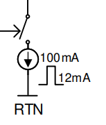
I reviewed the LM74722 datasheet and the I(PD_SINK) condition are defined in the device characteristics table but only for overvoltage while the "Load Disconnect Switch Control (PD)" section clearly state that they are also when the enable is low (and erroneously when Vs drops below V(VS POR)). There is no VS pin on the LM74722, but there is one on the LM74720. It seems also that there are some current values inherited from the LM74720-Q1 datasheet because the figure 8-2 in the "Load Disconnect Switch Control (PD)" section use the typical LM74720 I(PD_SINK) currents.
I reviewed the LM74720-Q1 datasheet and it seems that there was an attempt to better describe the behavior of the PD discharge switch. The "tPD_Pk" parameter tries to explain the conditions and duration in which the discharge switch is active.
In my humble point of view, even the LM74720 datasheet is not clear enough about the behavior and timing for the PD pin. A timing diagram with ALL the conditions should be added.
The timing characteristic for the PD pin is still missing in the LM74722 datasheet as this device is in a pre-production state.
Is it possible to get more information about the behavior of the PD pin for the LM74722-Q1? Clear conditions and detailed timing would be great.
Also, pass the comment that the datasheets should be updated. If we encountered problems with this interesting and new device, others will too.
Any other information, like the SOA of the discharge switch could be useful.
For now, we will add the recommended series resistor with the PD pin but we are unsure if it is a definitive solution and if the large output capacitance of our circuit could still cause the discharge switch to blow.
Best regards,
Eric