This thread has been locked.

If you have a related question, please click the "Ask a related question" button in the top right corner. The newly created question will be automatically linked to this question.

LM5121-Q1: will not start switching

Part Number: LM5121-Q1
Other Parts Discussed in Thread: LM5121

Hi there,

I have implemented a 55V 5A boost converter design using the LM5121 (stepping up from ~30-42V battery input voltage).

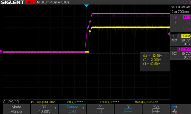
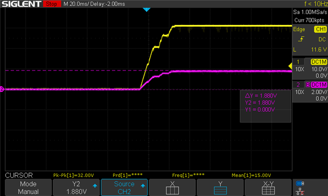
However, the design will not start switching - I only get the input voltage on the output. This indicates the disconnect MOSFET is working correctly, and I can see the gate does indeed have a voltage ~ 10V higher than V in.

Similarly, the bootstrap capacitor on the output has the expected voltage of ~ 10V higher than V in.

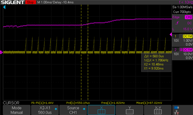
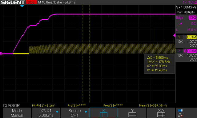
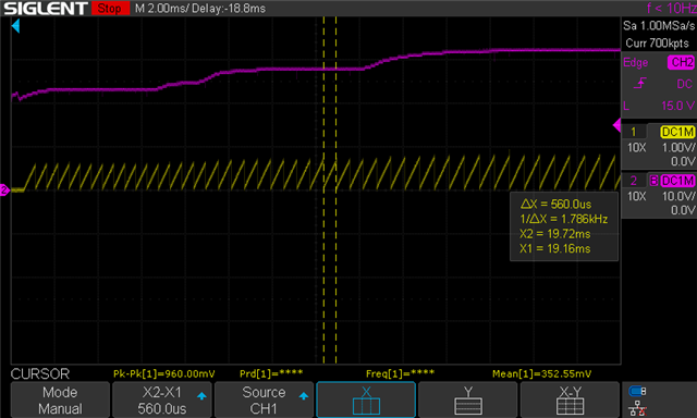
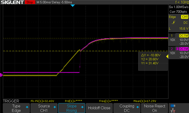
When I probe the Soft Start pin, I can see the converter starts to turn on, as the voltage on the capacitor starts ramping up. However, part way through the ramp it resets back to zero volts. As a result, I see a triangle wave on the soft start pin.

I have tried several different soft start capacitor values, and restart capacitor values (including tying reset to ground) but the regulator will not start switching.

Any ideas as to what may be the issue?

Thanks!

55V5A_Supply_LM5121-55V5A_LM5121.pdf

  • Hi Aidan,

    Thank you for using E2E forums, Could you please give me the complete design specs, Vin Typical and Fsw? and your minimum and maximum Input voltage is 32 and 42V I am guessing, is that right?

    Thanks,

    Haroon

  • Hi Harron

    The specs are as follows

    Vin(max) = 42V

    Vin(min) = 30V

    Vin(nom) = 36V

    F_sw = 500kHz

    Note that I have been doing my testing with an input voltage of 32V (and yes, the UVLO voltage is sufficiently high to enable to device)

    Regards,

    Aidan

  • Hi Aidan,

    I see, from what I can see your inductor is rated for 10A, is that the maximum current it can withstand, what is the rated saturation current of the inductor? from your design the peak inductor current can go up to 15A, so I think if your inductor is not rated for that current value there could be over current issue, is it possible for you to get the DG waveform during startup, alongside the RES and COMP pin waveforms as well?

    BR,

    Haroon

  • Hi Harron,

    Sorry I did not specify it on the schematic, but the inductor is the PA5433.153NLT, which has a rated current of 13.0 A, and a saturation current of 18.0 A. So far I have just tested this design without a load so I would not expect the saturation of the inductor to be an issue.

    Waveforms:

    DG (Yellow) and VIN (Pink)

    RES (Yellow) VIN(Pink)

    COMP (yellow) VIN (pink)

    COMP (Zoomed in)

    Soft Start (Yellow) VIN (Pink)

    Soft Start (Zoomed in)

    Thanks for your help,

    Aidan

  • Hi Aidan,

    Could you please also share the UVLO pin waveform?

    Thank you

    BR,

    Haroon

  • Hi Harron

    Sorry for the delay,

    Here is the UVLO waveform on startup

    Aidan

  • Hi Aidan,

    thank you for sending the waveforms.
    Haroon is currently out of office until the end of the week.
    He will get back to this thread as soon as he returned to the office.

    If you have any urgent questions, please let me know and I will see if I can be of assistance as well.

    Best regards,
    Niklas

  • Hi Aidan,

    Sorry for the delay I was on leave, regarding your waveform the UVLO waveform is the purple one or yellow? I am assuming it is the yellow one, is that correct?

    BR,

    Haroon

  • Hi Haroon,

    No, the yellow waveform is the input voltage (~32V) and UVLO is the pink waveform (~1.9V), which is well above the ~1.2V threshold.

    Aidan

  • Hi Aidan,

    Actually according to your schematics your UVLO threshold is 21.6V not 1.2V, the voltage divider at the UVLO pin determines the Turn on voltage for your device, you can see that in the datasheet section 7.3. it seems that your UVLO pin voltage is lower than the threshold and hence your device has not started up. I believe the EN_IN pin of the FET that is connected to the UVLO pin is causing the problem. Could you turn the FET high ohmic and see if your problem is solved?

    BR,

    Haroon

  • Hi Harron

    When I said 1.2V threshold, I meant the internal UVLO threshold of the LM5121 IC, as seen in the datasheet.

    I am supplying the circuit with a voltage of 32V, which thus results in the ~1.9V at the UVLO pin. As the voltage at the UVLO is above 1.2V, I believe the startup sequence should begin, and the regulator should begin operating.

    The FET (Q1), and the associated resistors (R3 and R4) are not populated, so have no affect on the operation of the circuit. Likewise, D1, R1 and R2 are not populated.

    Thanks,

    Aidan

  • Hi Aidan,

    Yes I understand, but your UVLO threshold is set up by your resistor, so they are not ineffective as you can see here in the image:

    the threshold for your design is 21.6V so until the voltage at UVLO pin has not reached 21.6V the device will not start switching.

    BR,

    Haroon

  • Hi Haroon,

    I think there is some confusion about the difference between input voltage threshold (V_IN(STARTUP) = 21.6V) and internal voltage threshold (UVLO threshold, 1.2V). There should never be 21.6V on the UVLO pin (it has an absolute maximum rating of 15V)

    I have set the voltage divider so that when the input voltage is 21.6V, the voltage at the UVLO pin is 1.2V (the internal threshold voltage of the IC). Thus any input voltage greater than 21.6V should turn on the regulator.

    In the waveforms I sent, I had an input voltage of 32V (yellow waveform), resulting in a voltage of ~1.8V on the UVLO pin (pink waveform), which is above the internal threshold voltage of 1.2V. This means the regulator should be on.

    Also, note I have measured the DG (disconnection FET gate voltage) as approximately 11V higher than the input voltage (i.e. 43V) which indicates the charge pump is running (note that VCC is also at 7.5V, above the VCC UV threshold). Also, if I decrease the voltage below ~21.6V, DG is reduced to VIN, indicating the regulator has turned off.

    Everything is indicating to me that the conditions for turning on the regulator have been met, and the converter is also trying to turn on (indicated by the soft start waveform).

    After some more probing around I did notice that (when unloaded) the output voltage tracks about 4V above the input voltage, but does not reach the desired 55V.

    Regards,

    Aidan

  • Hi Aidan,

    Sorry for my confusion, yes you are right the 21.6V is the minimum Vin threshold and the voltage on UVLO pin should be as you stated and it is correct in the waveform. The problem is the SS waveform which is not how it is supposed to be. Could you also send me one final waveform of Vout and Vin? 

    BR,

    Haroon

  • Hi Harron

    Here is V_out and V_in as requested. V_in is the yellow waveform, and V_out is the pink waveform

    5ms/division

    200ms/division

    It looks to me like the output is slowly being charged up, perhaps each time the regulator tries to restart?

    I also have attached a small load to it (~100mA) and this drops V_Out down to V_in, as I suspected.

    Regards,

    Aidan

  • Hi Aidan,

    I will get back to you as soon as possible, please give me some time.

    Thank you

    BR,

    Haroon

  • Hi Haroon,

    I have discovered the issue, the inductor was placed incorrectly (at 90 degrees to correct placement). This meant the inductor was acting as a short.

    Thanks for your time,

    Aidan

  • Hi Aidan,

    I see, so does that mean that you circuit was not working in no-load condition and that the current was too high reaching the current limit and hence the device was going into hiccup mode?

    BR,

    Haroon

  • Yep, I think that is what was happening.

    It certainly looked like it kept trying to restart due to an overcurrent condition.

    Aidan