This thread has been locked.

If you have a related question, please click the "Ask a related question" button in the top right corner. The newly created question will be automatically linked to this question.

LM2735: 3.7 V to 5V only regulates from Vin = 4.2

Part Number: LM2735

Hello,

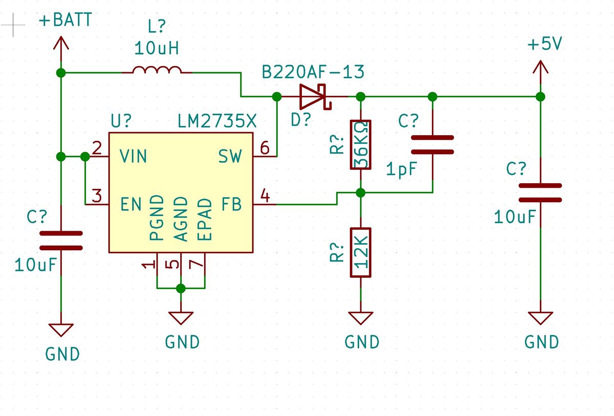
I have designed my own board for a battery-based application using the LM2735X (1.6 MHz). Vin = 3.7 V, Vout = 5 V, Imax = 1A. I am using a regulated voltage supply as input for the initial tests. The problem is that the output is only 5V once the input has reached 4.2 V. When applying lower input voltages, the current consumption increases significantly.

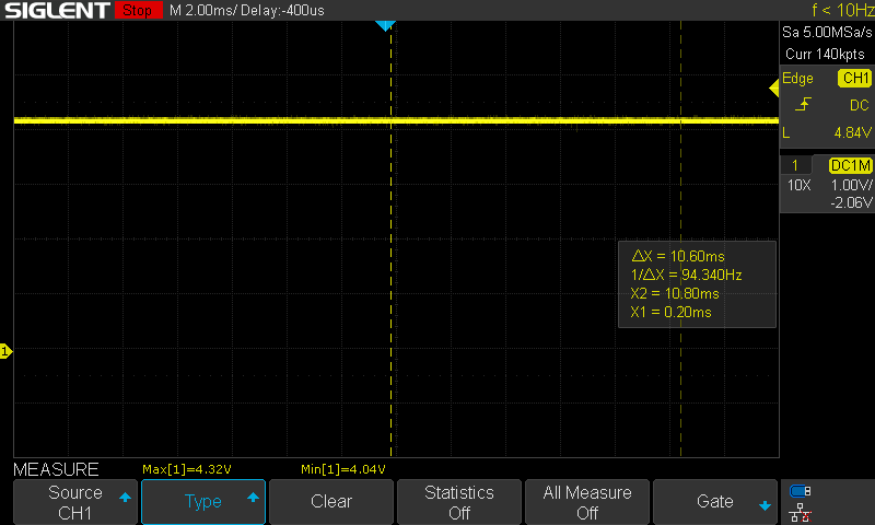
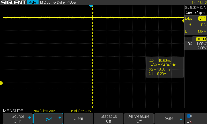
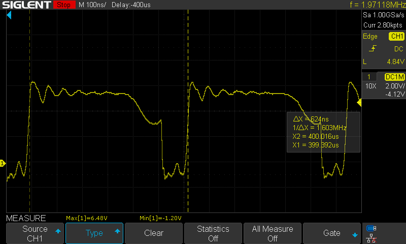
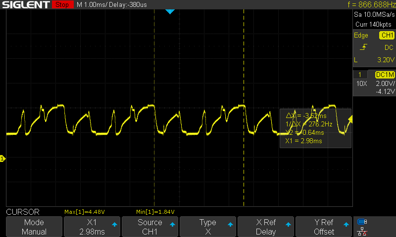
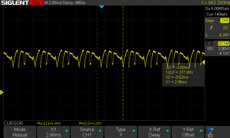
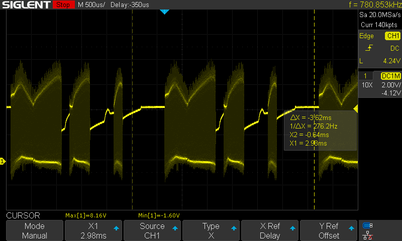
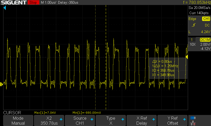
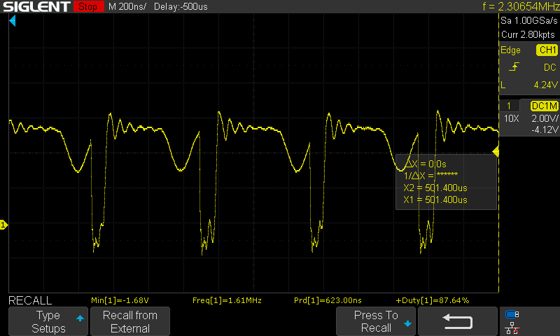
Please, find below an oscilloscope measurement of the Switching node

Do you have any thoughts on what could the issue be?

Thank you so much

Ignacio

  • Hi Ignacio,

    Thanks for reaching out.

    1. Can you show your schematic and layout here? 

    2. What is the effective value and saturation current of the inductor?

    3. Can you also take the waveforms of Vin, Vout, SW and iL?

    Regards,

    Bryce

  • Hi Brice,

    Thank you for your reply.

    1) Schematic

    2) Layout

    Note: the compensation capacitor is soldered over the resistor R2 (Sandwich).

    3) Inductor: Wurth 74477610. Imax 2.98 A, Isat = 3.24 A

    4) Waveforms

    4.1) Situation #1: Vin = 4.2

    Vin

    Vout

    VSW

    4.2) Situation #2: Vin = 3.7V

    Vin

    Vout

    VSW

    VSW --> Zoom

    I cannot measure the IL, sorry for that. My first guess is that the inductor value (10 uH) is too big for this application

    Please, let me know your thoughts

  • Hi Ignacio,

    Thanks for your clear scopes. Below are my comments:

    1. What is your input supply when you experiment? The battery or DC source? Why the input voltage is unstable at 3.7Vin?

    2. I think the inductor current has decreased to zero from the scope of SW in 4.2Vin-5Vout, please double check the inductor value. It will be very helpful if you can measure the inductor current by putting a wire between pad and inductor and probe it.

    3. From the scopes of 3.7Vin, the minimum input voltage has been smaller than UVLO falling voltage, which could shutdown the device.

    4. I have check the layout, the gnd of Cout is far away from GND pin, which increases the parasitic parameter of the switching loop. The loop parasitic inductance in high di/dt current path will generate high voltage spikes at output and across power MOSFETs. Suggest it put close to GND pin like recommendation. Also, suggest remove the copper under the inductor.

    Regards.

    Bryce

  • Hello Bryce,

    1. It is a DC source. It is stable but when I go down to 3.7 V when supplying the converter there is this variation. It disappears when I increase the power supply voltage to 4.2 V and the converter regulates.

    2. I have ordered new inductors, once I perform the tests I will let you know.  I am going to beg for a current probe or purchase one in the meanwhile Slight smile 

    3. I think so too.

    4. You are right, let's see what can I do with this PCB.

    I will keep you posted!

    Thank you so much

    Ignacio

    uctor current has decreas
  • Hi Ignacio,

    Thanks for your update.

    1. What is your supply current limit when you experiment? The minimum input current limit should not be less than 2A, assuming the efficiency is 0.8, Iin=5V*1A/(0.8*3.7)=1.7A. Please ensure that DC source current limit is enough.

    2. Can you repeat the unstable phenomenon on other boards? It's good if you can capture the inductor current waveform.

    Regards,

    Bryce

  • Hello Bryan,

    Here is my update:

    - I replaced the inductor with a 3.3 uH and 4.2 A.

    - I cut the power plane behind the inductor, so there is no ground plane floating there.

    - I added a capacitor at the output, so its ground connection is close to the GND pin of the boost converter

    It is working!! It regulates well with all the input voltage ranges.

    Thank you so much!

    Ignacio

  • Hi Ignacio,

    Congratulation! Very glad to know that.

    Regards,

    Bryce