This thread has been locked.

If you have a related question, please click the "Ask a related question" button in the top right corner. The newly created question will be automatically linked to this question.

TPS61170: TPS61170: PWM Control of the feedback voltage ( Output voltage).

Part Number: TPS61170

Hello friends,

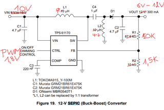
We want ot use the TPS61170 in SEPIC configuration with following requierements:

Input voltage : 10V
Variable Output voltage : 6V to 12V
The Output voltage shall be controlled via PWM.

Now the question:
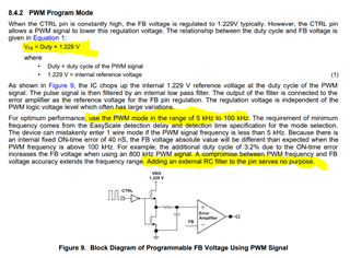
Wenn controlling the output signal via PWM,
How are the PWM input signal and the output voltage related ?
Is there a formula ?

Best regards.

  • Hi Delta,

    CTRL is actually EN function pin, which is used to enable (disable) the chip. If want to use this pin to adjust output voltage, Vout will be 0V when CTRL is 0V, and DC output voltage (set by R1 and R2) when CTRL is 1.8V. So the output will be PWM voltage output too. If DC voltage is required, one low pass filter is needed. Also please notice that because the chip's start up time is several ms, the PWM frequency is recommended to be set about 100-500Hz.

    Typically, there is another method to adjust Vout by changing FB sink/source current. Please find below app note for reference.

    Design of the Adjustable VOUT Boost Circuit

    Best Regards,

    Eric Yue

  • Hello Eric,
    Thank you for your answer and your suggestion to use multiple voltage dividers to generate
    different output voltages. That's what we've been doing, so far with another chip.

    But we are aiming to use the TPS61170 in SEPIC configuration to achieve the same result with less components
    and linearly by varying the PWM.

    The informations you are giving seems to be different from what is in the TPS61170 datasheet.

    1) In the Datasheet there is no need for an external RC filter.
    There the recommended frequency range for the PWM is 5kHz to 100kHz

    2) Going back to my original question, in a SEPIC converter the input and output voltage are related with: Vo/Vi = D/(1-D).
    So in my case with a fixed input voltage equal to Vi=10V.
    for Vo=6V ,  D=37.5%,
    for Vo=10V, D=50%,
    for Vo=12V, D=54.5%
    Will it work like this with TPS61170 or not?

  • "...So the output will be PWM voltage output too. If DC voltage is required, one low pass filter is needed..." 
    Why should one have at PWM signal at the output of a DC/DC converter ?
    How about the accuracy of the Output voltage, if we have to take it as a PWM filtered signal ?

  • Hi Delta,

    I think TPS61170 can meet you requirement. Sorry for forgetting TPS61170 has integrated low pass filter at CTRL pin. You can add PWM signal directly to CTRL pin and the output will be DC voltage. Please notice that I remembered the integrated low pass filter is not large enough to filter out lower frequency, such as below 20kHz, it is recommended to use larger PWM frequency, such as ~80kHz if possible.

    This method is to adjust REF voltage, the output voltage for SEPIC is Still VREF*(1+R1/R2), PWM signal can change VREF, which is D (PWM signal duty cycle)*1.229V. 

    The power stage duty cycle is Vo/Vi = D/(1-D) which is different from PWM signal duty cycle.

    You can set output voltage by 12V using divided resistor and adjust PWM signal to decrease output.

    Best Regards,

    Eric Yue

  • Hello Eric,

    Thank you for your answer :

    " ...This method is to adjust REF voltage, the output voltage for SEPIC is Still VREF*(1+R1/R2), PWM signal can change VREF, which is D (PWM signal duty cycle)*1.229V. The power stage duty cycle is Vo/Vi = D/(1-D) which is different from PWM signal duty cycle.You can set output voltage by 12V using divided resistor and adjust PWM signal to decrease output..."

    My understanding is that the SEPIC configuration with theTPS61170  is useless when it comes to adjust the output voltage using the PWM.
    The function you have described it that of a Boost-converter whose Output can be reduced using the PWM.

    Did i get it right ?

    Best regards

  • Hi Delta,

    No matter what method is used, if the output voltage is lower than input, the boost topology cannot meet the requirement.  Even set output voltage lower than input by changing REF voltage, the boost topology will limit this voltage transfer. For the power stage spec, Input voltage : 10V; Variable Output voltage : 6V to 12V, SEPIC topology is needed. 

    Best Regards,

    Eric Yue