This thread has been locked.

If you have a related question, please click the "Ask a related question" button in the top right corner. The newly created question will be automatically linked to this question.

LM51561H: VCC Pin Connection

Part Number: LM51561H
Other Parts Discussed in Thread: PMP22764,

Hi Team,

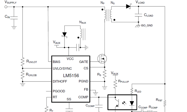
We are using LM51561HPWPR into our design to generate isolated 52V from 24V input power supply. LM51561HPWPR EVAL user manual shows that the VCC pin is connected with Auxilary winding of the flyback transformer.

Other reference design such as PMP22764 which uses LM51551DSSR shows that the VCC pin is connected with Auxilary winding of the flyback transformer. Below is the link for the PMP22764 ref. design-

https://www.ti.com/tool/PMP22764

Into the datasheet of LM51561H and LM51551D it is mentioned that the VCC is the output of the internal power regulator. Please refer to below image-

Below are our queries-

1) Why VCC pin is connected to Auxilary winding of the flyback transformer? As per description into datasheet VCC is an output pin.

2) For isolated DC-DC design what is the recommended way to use the VCC pin of LM51561H?

Regards,

Aditya

  • Hello, 

    Thanks for reaching out. Connecting the VCC pin to an AUX winding is optional and it helps decreasing the internal power dissipation of the device. A detailed description for this type of connection can be found at page 15 of the datasheet ( figure 9-7 https://www.ti.com/lit/ds/symlink/lm51561h.pdf ).

    Kind regards,

    EM

  • Hi Em,

    Thanks for your response. In Flyback topology, what will be the power consumption of LM51561H when using external power source at VCC pin (using an auxiliary winding)? Also, please let us know the power consumption of LM51561H if we don't use external power source at VCC pin.

    Regards,

    Aditya

  • Hello, 

    Thank you for your message. At page 28 of the datasheet (Section 10.3.2.8 Efficiency Estimation) you can find the estimation of the sum of losses in the device from eq. 20. Let us know if you need further help. 

    Kind regards,
    EM 

  • Hi EM,

    I checked the power loss equations provided on page no 28 of the datasheet and did below calculations for our application-

      Vbias 32 V (Max intput volt. is considered)
      Ibias 0.00058 A  
     Losses caused by quiescent current Piq 0.01856 W  
      Qg 0.000000083 Coulomb  
      Fsw 146300 HZ  
    Gate driving loss Pg 0.3885728 W  
    Losses in the device Pic 0.4071328 W Internal VCC regulator is used
    Losses in the device Pic 0.01856 W External power supply is connected at VCC pin to drive the power MOSFET

    Is calculated Pic is correct in both cases: With internal VCC regulator and without internal VCC regulator (external power supply is provided at VCC pin).

    Regards,
    Aditya

  • Hello Aditya,

    If you supply VCC directly, you can use VCC voltage for calculating equations 20 and 21 instead of Vbias in this case. But you need to make sure that the voltage you supply is higher than the internal regulation voltage, otherwise you split the current for the switch between Vbias and VCC.

    Best regards,
    Brigitte