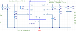
Feedback (FB) pin sitting at 0.65 V resulting in the output voltage being below the desired 3.3 V. Output voltage is currently at 2.65 V.

-
Ask a related question
What is a related question?A related question is a question created from another question. When the related question is created, it will be automatically linked to the original question.