This thread has been locked.

If you have a related question, please click the "Ask a related question" button in the top right corner. The newly created question will be automatically linked to this question.

UCC28180: ISENSE is open

Part Number: UCC28180

Hello,

We are making a power supply circuit using UCC28180.

When I made a circuit according to the circuit of EVM-573, the IC does not work at all.

Vcc is 14V input.

the FET is not oscillating because the gata signal is not output,

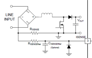
If you check with the IC removed from the circuit, ISENSE is open.

A diode is inserted between ISENSE and GND to prevent inrush current.

A diode is RB070M-30(Rohm).

I don't know what is the cause.

Please let me know if there is a possible cause.

  • Hello Asai San,

    Thank you for your interest in the UCC28180 PFC controller.

    When you say that ISENSE is open, are you saying that you believe the ISENSE pin on the controller is damaged?  If so,

    1. What do you mean that it is "open"?  I'm not sure if you suspect damage to the ISENSE device pin.

    2. How did you determine that it is open?

    3. Is the diode between ISENSE and GND connected as in the diagram below?

    4. What is the value of RISENSEfilter?

    5. What is your peak current?

    6. What is the value of RISENSE?

    Regards,

    Ray

  • Hallo Ray,

    Thank you for response to my question.

    1.  "open" means "opened circuit"


    2. I used a diode test from a multi-tester (FLUKE 115).

        A normal IC 3pin(ISENSE) outputs about 0.6V.

        A abnormal IC 3pin(ISENSE) showed "OL"

        The other pins output similar voltage values for both ICs.

    3.  Yes.

    4. the value of RISENSEfilter is 200Ω.

    5.Peak current is 37.6A.

     This peal current is intended to be an inrush current.

        Actually, I think it is a little lower.

    6.the value  of EISENSE is 30mΩ.

    I think the circuit I made is destroying the IC.

    I replaced the IC mounted on a normal EMV-573 with my circuit.

    Even if I put VCC, there is no reaction.

    And when I replaced the IC with EVM-573 again, it does not work. 

    Regards,

    Asai

  • Thank you for your reply Asai San.

    The answers to 1, 2, 3 & 4 above are clear.

    Regarding 5:

    • You need to determine what your actual peak current is during inrush and during normal operation to properly size your components.
    • EVM-573 was not designed for such high currents (peak power is 360W). For example, the inrush current for the EVM is 6.8A typical. If you followed the EVM design, why is there such a big difference?

    Regarding 6, RISENSE:

    • Is RISENSE damaged?
    • What is the power rating of RISENSE?

    Are any other components damaged?

    Please fill out a design calculator with your design targets and check against your component selections: https://www.ti.com/lit/zip/sluc506

    Regards,

    Ray

  • Hallo Ray,

    Regarding 5:

    Sorry , I made a mistake in peak current.

    The first peak current  (Inrush Current) is designed to be about 20.7A.

      →NCT thermistor between AC lines is 8Ω×2

          AC264V×√2  /  16Ω  ≒20.74A

    ーーーーーーーーーーーーーー

    Steady peak current (Actual Maximum Inductor Peak Current) is designed to be about 7.0A.

    Regarding 6:

    RISENSE is not damaged.

    The power rating of RISENSE is 3W.

    ーーーーーーーーーーーーーー

    There are no damaged parts other than the IC.

    Thank you for sending the design calculator. I will fill out it.

    Regards,

    Asai

  • The ISENSE pin can only handle +/1mA of current. Check your schematic and component values to see how this might be possible on your design.

    Ray

  • Hallo Ray,

    This problem has been resolved.

    The cause is a resistance value error.

    R9 ~ R11 of EVM-573 had 3.3MΩ instead of 332kΩ.

     I confirmed the switching normally and confirmed the boost up to 390V.

    There is no IC damage,too.

    Thank for dealing with my problem.