This thread has been locked.

If you have a related question, please click the "Ask a related question" button in the top right corner. The newly created question will be automatically linked to this question.

TPS61183: fails to drive isolation FET transistor

Part Number: TPS61183

Hello

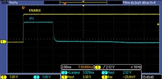
I mounted led driver TPS61183 on a board using schematic with isolation FET transistor shown in page 10 of TPS61183 datasheet.

I also followed the recommendations in paragraph 8.2.2.3, page 18 of the same datasheet.

The input power is 5V connected to the Source of my PMOS (Si7617DN). 

A 100KR is between the Source and Gate. Gate is connected to FAULT pin, and the output (inverse diode and inductor) are connected to the Drain of the FET.

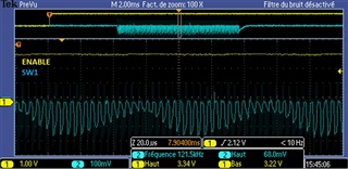
The PWMIN signal is controlled by the microcontroller with a frequency of 1KHz, and variable duty cycle.

4 leds strings are used (IFB1..IFB4) and IFB5 and IFB6 are pull to 0V via a 10-Kohms resistors.

EN signal is driven high by a microcontroller which also provides the PWM signal on PWMIN pin.

ISET is pulled down by a 200K resistor to get 6mA per string.

I put a voltage divider (100K/5,62K) towards OVP.

RFPWM/MODE is pulled high via a 1K resistor.

RFSW = 499Kohms

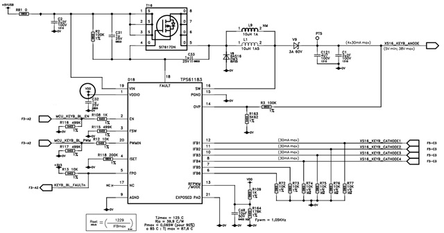
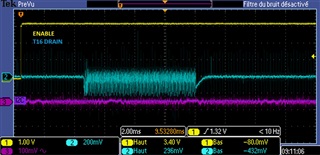
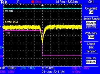
When I set EN signal to logical 1, I see a slight decrease (less than 200mV) on FAULT pin and it goes back to 5V.

I conclude that the FAULT pin of the TPS61183 fails to pull the Gate of the transistor to 0V.


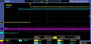
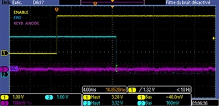
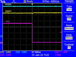
With this schematic, the TPS61183 systematically goes into error and pulls its FPO pin to 0 and the output voltage (connected to the leds strings anode) is 0V.

Can you help me on what could cause this error ?


Regards

  • hi David

    First of all, can you help clarify the exact output voltage in the test, 38V?

    please try to remove R74-R77 and check the result. 

  • Hi Mason,

    Thanks for your fast answer.

    R74 through R77 are Not Mounted (marked NM on schematic). Only R72 and R73 are mounted since I dont use this 2 led strings.

    The expected voltage is 31V 

    Regards

  • hi David

    thanks for the information. Then I think R164 should also be NM as you mentioned mode pin is pulled up by a 1k resistor, which means device works in direct PWM mode.

    Can you help provide start-up waveforms of pin Fault, pin SW, pin IFB1, drain voltage of T16? I would like to check the start-up behavior first. thanks

  • Hi Mason,

    R164 is also NM not mounted. 

    Following are the waveforms when ENABLE signal goes high:

    Regards

  • hi David

    Based on the waveforms, I think the timing is that Fault is not fully pulled down, device is trying to regulate for several switching cycle but cannot raise output voltage as input is not connected and then shut down. 

    can you help zoom in Fault pin waveforms? pls put fault pin, VDDIO pin, FPO pin in the same pic. 

    some other questions: 1) any behavior difference with different PWM duty cycle? 2) any behavior difference with higher input voltage like 10V  3) what is purpose for C33? can you have a try to remove this? 

  • Hi Mason,

    1) I tried with different PWM duty cycles and then removed R109, and mounted R164 to have a 1KHz PWM : still not working

    2) I will try with 10V and let you know

    3) C33 slows down the commutation of the transistor to limit the current inrush. I already removed C33 from the board, It did not solve the problem.

    Following are the required waveforms:

    Regards

  • hi David

    thanks for your feedback. Some of my findings from the waveform:

    1) From the second pic., it seems the voltage level of VDDIO is ~5V (CH2) while normal range of VDDIO should be 3V-3.6V. Would you mind double checking this?

    2) also from the waveform, it takes several ms to discharge Fault with only ~200mV and this may trigger certain fault. I suspect the paralleled capacitor C31 is too large. Please try to reduce this cap to 10nF or even 1nF and see if any difference.

  • Hi Mason,

    I changed the capacitor C31 from 1uF to 1nF and it solved the problem.

    Thanks for your support.

    Regards