This thread has been locked.

If you have a related question, please click the "Ask a related question" button in the top right corner. The newly created question will be automatically linked to this question.

TPS65130: Question on Current limit and BSW operation

Part Number: TPS65130
Other Parts Discussed in Thread: TPS65131

Hi Expert,

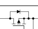
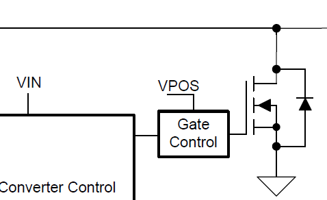
I have some questions regarding current limit in TPS65130. Customer had drew current over current limit which is 800mA and IC didn't seem to be switching as it exceeded limit. However the BSW pin didn't go to High at the same time. Since PMOS is ON, the input voltage and current is directly connected output.

Customer thought TPS65130 had an OCP feature and expected BSW to pull High to turn off the PMOS and disconnect output from input. But it didn't work like that.


Q1. Isn't BSW pin supposed to be High at overcurrent condition to turn off PMOS? 

Q2. Then, in over current condition, Is it normal operation that the IC stops operation and PMOS stays ON so the input and output are directly connected?

Q3. How to prevent output from over-current(over 800mA) in this customer's system? Do they need external circuits or IC?

Thanks,

Jay

  • Hi Jay,

    What customer observed is correct operation of TPS65131. The current limit is cycle by cycle boost switch current limit (not the output load current limit) and if this limit is exceeded, internal boost switch is turned off immediately but the input to output connection remains through the external boost diode (D3302 in the schematics you attached). The BSW signal for the switch Q3303 is only to disconnect the input from the output when the TPS65131 device is disabled by pulling low the ENP input of the device. This is to prevent the battery from draining when TPS65131 is disabled.

    Kind Regards,

    Liaqat

  • Hi Liaqat,

    Well noted. I got two more questions.

    1. Is the external rectifying diode mandatory? It seems to be working without the diode(D3302) as a internal diode is parallel to the rectifying diode but I'm not sure whether the internal one could be enough to hold up or not. 

    2. What about OC in negative output side?Unlike to positive, I think negative output is disconnected to input as soon as current exceeds the limit. Am I correct?

    Best regards,

    Jay

  • Hi Jay,

    1. External diode is needed as part of the boost power stage that works with the internal boost switch shown below so, yes, it is needed.

    The switch you showed in your post is not the boost switch but rather a switch for a mechanism to draw current from output back to input so as to enable constant frequency operation during very light load. Please see further description in section 7.3.1 of the datasheet.

    2. Inverting buck-boost (negative) converter switch current limit works on a cycle by cycle basis, similar to boost switch, but since this switch is in series with the output, the output gets disconnected from the input. In the case of boost, the switch is in parallel with the output hence it does not disconnect the output.

    Kind Regards,

    Liaqat