This thread has been locked.

If you have a related question, please click the "Ask a related question" button in the top right corner. The newly created question will be automatically linked to this question.

TPS61169: TPS61169 - Feedback voltage tolerance and LED current for different dutycycle

Part Number: TPS61169

I would like to know the feedback for 2 questions

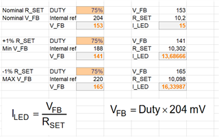
1. Could you please provide feedback voltage tolerance for higher temperature, ex 70 C (please find the attached screenshot - calculated value)

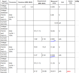
2. As per the datasheet, calculated the led current with feedback voltage for different duty cycle (10,30,50,75,100).

   In the design , totally there is 4 led in the string.  therefore led current and voltage are measured in testing.( Attached screenshot - Measured value)

   For lower duty-cycle, the measured values are out of the calculated range. Could you please able to provide the explanation or reason for this deviation?

  • hi Saranya

    The calculated current value under different duty cycle should be under the condition that control loop exactly regulate output current to reference. However, there is control accuracy related to internal EA offset and normally higher LED current (larger duty cycle) results in better accuracy.

  • 1. LED current value (with different duty cycle) is calculated as it is mentioned in the datasheet. So However I would like to understand the how the output current should be calculated for low duty cycle. Is there any other factors to be included to calculate accurately? What would be the reference value how it will vary from the output current for lower duty cycle?

    2. Could you please explain about the control accuracy and internal EA offset for better understanding? I would like to know  justification, based on what factors the for lower duty cycle the accuracy will be lesser? it is somewhere stated in the datasheet?

    3. Could you provide the feedback voltage tolerance for higher temperature

  • hi Saranya

    pls see below diagram which is also given in the datasheet and notice GM amplifier that has two inputs, one Vref and another FB voltage. datasheet gives the range of Vref 188mV to 220mV @100% duty. We can expect a proportional result under other duty conditions(Vref @ d%=Vref@100%* d%). But this does not mean we can exactly get FB voltage=Vref. For example, GM amplifier offset means there exists small output even when input differential signal Vref-VFB =0. This GM offset contributes part of control error that system can not exactly control VFB to Vref. The situation can be worse under quite small duty cycle.

    currently, we cannot give the accurate formula for low duty cycle.   

  • Hello Mason Wang

    Thanks for the clear explanation.

    Could it be possible to provide the feedback voltage (with tolerance) at higher temperature?

  • hi Saranya

       The error of regulated feedback voltage is not only related EA offset, but also external power components. It is hard to provide under different conditions.    

  • Feedback voltage will not be constant for over all temperature. How to evaluate the LED current at higher temperature? Generally in all the other Drivers/Converters the feedback voltage vs temperature will be provided.

  • ok, I will check if there is additional data available beyond datasheet internally. would you mind sharing some background on the project? It seems the product is sensitive to temperature. thanks

  • For all the automotive products, operating temperature range would be -40 to 80 degree. Any product that needs to be evaluated for this temperature range, in general. Back-lights are been used in the project for display, So need to justify/ evaluate the led current at higher temperature?

  • thanks for your information. I will feedback once I have some information.

  • hi Saranya

    after checking, we only have Vref data available which is also shown in the datasheet 188mV-220mV, and this is valid in the temperature of 25deg-125deg.