


hi team,
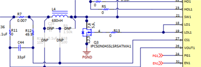
I see EVM and I wonder if you directly use the DCR of the inductor-L4 as a current sampling loop?
please tell the function of R17、R18、C29、R9 beside L4.
hi team,
I see EVM and I wonder if you directly use the DCR of the inductor-L4 as a current sampling loop?
please tell the function of R17、R18、C29、R9 beside L4.

