This thread has been locked.

If you have a related question, please click the "Ask a related question" button in the top right corner. The newly created question will be automatically linked to this question.

TPS7A4001: Schematic review

Part Number: TPS7A4001
Other Parts Discussed in Thread: PSEMTHR24EVM-081

Hi All,

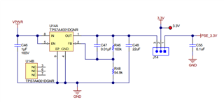
please can you review our schematic with TPS7A4001 LDO

Vin = 56V

Vout = 3.3V

Iout = (12mA TPS23881RTQ + 11.3mA ISO1644DW) ~25mA max ; Iout_typ = 15mA

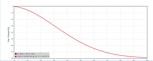
-> is one 10uF 25V 1206 X5R ( effective @ 3.3V -> 9.5uF) enough or should i leave the additional footprint C61 and populate it with 10uF 25V 1206 X5R?

-> on the input is 1uF 100V 1206 X7R (effective @ 56V -> 470nF) is this ok or do i need additional C66 to be populated with 1uF 100V 1206 X7R?

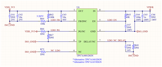
in TIDA-050026 there is similar configuration of LDO and only one 1uF 100V 1206 X7R is used

-> as the 56V comes from a isolated flyback converter do i need some LC or Ferrite bead filter on the input of TPS7A4001?

Best Regards,

David.


  • Hi David, 

    The configuration looks ok. This device needs an effective capacitance of 4.7uF for the output, therefore, having 9.5uF should be sufficient. In the case that this is really a concern, perhaps adding a 1uF rather than a 10uF. 

    As for the input, the required minimum capacitance is 1uF, therefore, another cap is required, perhaps a 1uF||100nF with a 2.2uF. 

    How much ripple is expected from the flyback converter? 

    Best, 

    Edgar Acosta

  • Hi Edgar,

    if i use 1u || 1u || 100n then this is effective over 1uF, but how do you explain this TI reference design that has only 470nF effective capacitance on input?

    PSEMTHR24EVM-081 /  TIDA-050026 / PSIL081

    We expect 100mVpp like on this design

    https://www.ti.com/lit/ug/tidt115/tidt115.pdf?ts=1656057612473

    Best Regards,

    David.

  • Hi David, 

    Reference designs serve as a starting point and guidance to customers. 

    In addition, the reference design only shows a 1uF rated for 100V, although an estimation could be made, it is hard to tell how much it will de-rate without exact part number.

    It is common to see that a capacitor is selected with the exact minimum capacitance value. 

    With 100mVpp, you should be ok without any filter.

    Best, 

    Edgar Acosta

  • Hi Edgar,

    here is the PN from BOM 

    C46 4 1uF 12061C105KAT2A AVX CAP, CERM, 1 μF, 100 V,+/- 10%, X7R, 1206

    and VPWR is 55V

    Best Regards,

    David.

  • Hi David,

    Yeah, I looked at the capacitor and it will derate more than 50% @55V, closer to ~400nF, even lower than the 470nF estimation. 

    As previously mentioned, reference designs are to serve as guidance and not as a final product. 

    Just make sure enough capacitance is placed i.e 1uF||2.2uF||100nF or 10uF||1uF||100nF. It is recommended to use 10uF capacitor for better AC performance. 

    Best, 

    Edgar Acosta