This thread has been locked.

If you have a related question, please click the "Ask a related question" button in the top right corner. The newly created question will be automatically linked to this question.

TPS552882EVM-400KHZ: TPS552882RPMR

Part Number: TPS552882EVM-400KHZ
Other Parts Discussed in Thread: TPS55288, TPS552882

Dear Madam/Sir,

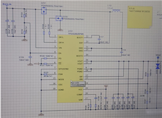
We are using TPS552882RPMR in one of our new designs. We made our design suitable for the TPS552882EVM-400kHz circuit. Vin: 6.5 to 24V Vout: We want to get 7V, but we can't get any output. When we examine it, we think that the IPZ40N04S5L4R8ATMA1 fets are not activated. But we are not sure. We also reviewed the user guide document for Layout and verified it with a short circuit. I am sharing our circuit in the attachment, where do we make mistakes, if you have any suggestions, we can try. Or can I simulate this part in Pspice or Tina? When I try to search for a part in Pspice, it gives an error. I don't know what I can do about it, but I will try it on a different computer.

  • Hi Sir,

    Thank for reaching out on E2E.

    Please note that TPS55288 needs I2C to configure the register first so that the device could start switching. Did you configure the I2C registers?

    If you don't have a MCU in your system, suggest using TPS552882. This device starts working once it is powered on and enabled.

  • Hi,

    Thanks for reaching out.

    1. Can you also upload your layout file here? So we can help check your layout. And what is the short circuit you mentioned in the layout?

    2. What is the maximum output current of the design? Can you take the waveforms of the SW1, SW2, iL, Vout? You can measure the VCC voltage to see if the device is powered on.

    3. You can simulate this part with TPS55288 PSpice model TPS55288 Encrypted PSpice Model using 'PSpice for TI'.

    4. I have check the schematic, the MOS is OK with this design. From the FB divider resistor, the target output should be 1.2/25k*125k=6V.

    Regards,

    Bryce