This thread has been locked.

If you have a related question, please click the "Ask a related question" button in the top right corner. The newly created question will be automatically linked to this question.

UCC28C45: Instability on COMP signal?

Part Number: UCC28C45
Other Parts Discussed in Thread: TL431

Team,

Customer has made a Flyback design based on UCC28C45:
    Vin : 85 to 265V, Vout = 17.5V, Iout = 0.7A
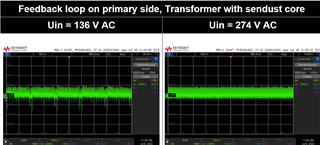
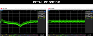
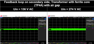
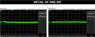
The design shows on the COMP output an oscillation tendency or instability depending on the input voltage.
-What could be the cause?
-Can it be because we exceed the current limit of the output?

Here are some oscillscopes plots.

Thanks in advance,
A.


  • AnBer

    If the current limit is being exceeded during normal operation, please adjust the value correctly. Use TI Power Stage Designer to verify the power stage values are known to be valid, then stabilize the loop without the opto at first. Here's an approach that's always worked for me:

    1. Stabilize the voltage loop by temporarily placing a dominant pole in the feedback of the voltage error amp. A 100nF cap between COMP and FB should accomplish this. The regulation and transient response will not be good at this point but that's ok - the voltage loop will be guaranteed stable.
    2. Next, stabilize the current loop. Make sure the CS resistor is the correct value for the given load range you are planning and the Lmag you've chosen for the transformer. Check the CS signal over the full line/load range, add about 20% design margin above worst case corners, adjust your RC filter value corner frequency to minimize ringing but still introduce a linear ramp to the CS input. 
    3. Once the CS signal is stable, go back and bias the opto/TL431. TL431+opto is a very popular feedback technique for switching converters and you can find many good design resources and YouTube videos on how to properly set it up.
    4. Once the opto/TL431 are properly biased and transferring the error signal to FB correctly and operating over the full dynamic range, remove the short between secondary and primary and connect the opto/TL341 back into the feedback. The converter should now be stable but will still need compensation of the voltage loop.
    5. To compensate the voltage loop, use the TI Power Stage Designer or Excel or MathCad or your simulation tool of choice to model the loop. Otherwise, if you have access to a network analyzer, you can measure the open loop gain/phase and build the compensation in the lab to shape the control loop response until you achieve your desired gain, crossover and phase response.
    6. Once the CS loop, voltage loop, opto/TL431 are all stable, begin to systematically add back the circuit blocks that were previously disconnected

    Regards,

    Steve M