This thread has been locked.

If you have a related question, please click the "Ask a related question" button in the top right corner. The newly created question will be automatically linked to this question.

TPS2400: SLVA163 low-side switch implementation problem and TPS54360 becomes hot to the touch

Part Number: TPS2400
Other Parts Discussed in Thread: TPS54360,

To Whom it May Concern,

We implemented the low-side switch circuit from your SLVA163 application note and are finding that the MOSFET (PMV213N) is being randomly being damaged in the application.  The voltage input to the DC-DC converter is rated from 42V to 48V where the over-voltage circuit was added as customers were hot plugging in the devices.  The output of the DC-DC (12Vdc) is connected to an external LCD monitor that draws approximately 1.5A continuously.

Input current (42Vdc): 490mA

Output current (12Vdc output): 1.5A

1. The PCB area where the TPS54360 DC-DC converter is very warm to the touch, we measured approx. 48degC on the case top and about 53degC on the PCB by the chip. We followed the datasheet recommendation for thermal pad dimensions and via's.  I am assuming changing the top and bottom copper from 1oz to 2oz may help lower the temperature but I am not sure how much.

2. We are having several units being returned from the field for issues related to the over-voltage circuit consisting of the TPS2400.  Many of the issues seem to be related to the MOSFET where the component is obviously damaged.  One unit measured a short between the drain and source.  One of our engineers changed the filter capacitor ground connection from your application not from the drain side to the source side as they thought the issue was related to the capacitor connection.

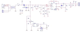
It appears the TPS2400 is working as designed, however we are having issues trying to figure out why the MOSFET's are not working on some of these units.  Attached is a schematic of the power supply circuit.  I am hoping someone could provide us with some recommendations on why the circuit is subject to the MOSFET being damaged as well as why the TPS54360 is becoming over-heated (close to max temp of device).
Thank you in advance,

Melody Witter

  • Hi Melody Witter,

    Welcome to E2E!

    We will look into this and get back tomorrow. 

    Best regards,

    Rakesh

  • Hi Melody Witter,

    At top level, the schematic and component selection looks good.

    It looks to me the inrush current stress might be causing the  MOSFET (PMV213N) to damage. you have 100uF+2*2.2uF right at the input of DC-DC converter. Can you capture test waveform of Vin, input current and GATE of PMV213N during worst case hot-plug event and share us for review.

    If needed, We need to adjust gate-to-drain capacitance on PMV213N to limit the inrush currents.

    Best regards,

    Rakesh

  • Hi Rakesh, 

    Thank you for your quick responses.  Attached are some scope plots we captured that I am hoping will help you although they were captured when plugging in the supply with the LCD connected (not a hot-plug event).  I am currently out of the office so will try and capture Vin when I am back and can try measuring when plugging in the LCD display power cord to our device when it is already powered (hot-plug event). 

    Note that the input current measurement may be difficult for us to measure as we do not have much equipment to do proper measurements.  Will the voltage measurement across the drain/source of the FET suffice as it was captured at first power up and use the typical resistance in their datasheet to calculate the current?  If not, would you be able to suggest a method that we can use to be able to measure the input current?

    The attached scope images were triggered on the TPS-2400 gate that connects to the gate of the MOSFET (CH1).  For all measurements Vin was 41.7Vdc to the input of the DC-DC converter.  All results were obtained powering and removing power for the entire system. 

  • Hi Melody Witter,

    Ron of the MOSFET varies during the startup as Vgs builds up. So, measuring drain - source voltage may lead to wrong information.

    Please try to source a current probe for measurements. Alternate option can be to insert a lower value resistor ( in the order 100mOhm) in the path and measure voltage.

  • Sorry about that, I had a total brain malfunction (LOL).  Anyway, I have been trying to measure the current but unfortunately our scope's math function is not working.  That being said, while I was trying to do the measurements the power supply we were using blew its fuse during the measurements.  The fuse also blew a couple of other times during testing but I had originally thought that it was something I connected wrong.  The fuse rating is 1.6A so your original suggestion of inrush current seems to agree with the 1.6A fuse being blown?

    Attached are voltage measurements of the TPS2400 GATE (CH1) and the 48V supply input as you requested. As discussed above, unfortunately I am unable to capture current waveforms for you to review (see above).  The first plot is with a regular power on event and the 2nd scope plot shows the effect of a hot plug event.

  • Hi Melody Witter,

    Thanks for sharing your additional observations.

    Yes, the main fuse might have blow due to inrush currents. 

    Please increase D-G capacitance C29 to 22nF for PMV213N and use 1kOhm for R48. It should help to reduce the inrush.

    Best regards,

    Rakesh