This thread has been locked.

If you have a related question, please click the "Ask a related question" button in the top right corner. The newly created question will be automatically linked to this question.

TPS61322: Schematic Review

Part Number: TPS61322

Hi TI Teams,

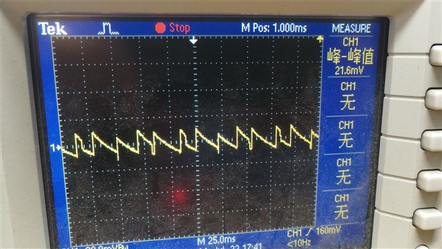
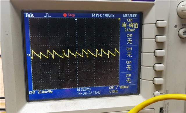
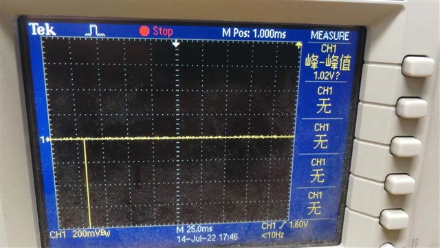
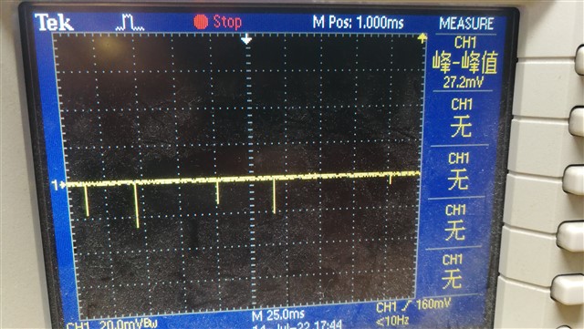
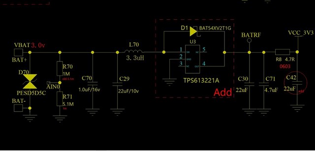
We found that the two capacitors C70 and C71 can be easily damaged, and returned to normal after replacing them. The following is our schematic of TPS613221A, please help to check if there is any problem in the circuit design, or do you have any better suggestion for this.


Thanks,

Best Regards

  • Hi Lumina,

    Capacitors can be damaged due to over voltage, over current or soldering.

    Can you forward the layout file here? And please forward the waveforms of Vin, Vout, iL and SW.

    Regards,

    Bryce

  • Hi Bryce,

    The waveforms of Vin, Vout, IL and SW are shown as below.

    1) 3.0V Vin waveform

    2) 3.3V Vout waveform

    3) IL waveform

    4) SW waveform

    Thanks,

    Best Regards

  • Hi Lumina,

    Thanks for your reply.

    Can you take the iL, SW, Vin, Vout in the one scope screenshot? I think the waveforms above are in different work conditions or the time scale is too large to capture the iL and SW waveform. You should change the scale to several us so I can see several switching cycles.

    Also, please forward the layout file here.

    Regards,

    Bryce