Hi Team,
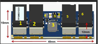
Please help here in providing the thermal breakout details for components available in the TPSM831D31MOA module at full load condition.
Thanks & Regards,
Prasad Tatar
Hi Team,
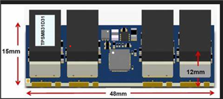
Please help here in providing the thermal breakout details for components available in the TPSM831D31MOA module at full load condition.
Thanks & Regards,
Prasad Tatar