This thread has been locked.

If you have a related question, please click the "Ask a related question" button in the top right corner. The newly created question will be automatically linked to this question.

BQ76200: How to connect high power ground & low power ground?

Part Number: BQ76200
Other Parts Discussed in Thread: BQ76920

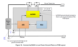
Hi, it would be helpful if anyone assist me in understanding low power and high power ground. In the below picture, what is the meaning of the statement "Low power ground and high power ground are connected here."?

Does it mean 'Battery pack -ve is connected to MUC ground, AFE ground & BQ76200 ground' commonly?

Or Should I take separate line from battery pack -ve through Rsense for load?

Thanks

  • Hey Kumar, 

    Low power ground and high power ground mean analog ground and power ground. The high power ground and low power ground should be connected in layout. The diagram just emphasizes connecting the ICs to the ground plane of the IC to help with noise.

    Thanks,
    Caleb

  • Hi Mr.Caleb,

    Firstly thanks for the information.

    I am working on 48V BMS application system, I have been using BQ76200 in one of the design where the Bq76200's ground is connected to high power ground on PCB directly and the same ground is connected to low power ground( 5V operated MCU's ground) through '0' ohms(0603) resistor. On testing along with the load(inductive 1KW motor), the CP EN pin was enabled initially, CHG EN & DSG EN pins were also enabled, load is ON. The device was working normally. Two "10K NTC's"  were placed near the MOSFET drain to monitor the temperature. The MCU pulled the CHG EN & DSG EN pins low during the mosfet's cutoff and makes the load OFF. On mosfet's cutoff recovery, I noticed spark on one of the NTC & '0' ohms resistor was burnt(open). The device is disconnected from the power(48V).

    Later on inspection of the PCB board, found that

    1) BQ76200's BAT pin(PIN 2) was showing short with respect to the Vss(High power ground). Also, CP EN pin(PIN 5) was showing the short w.r.t the Vss(High power ground).

    2) MCU's CP EN pin was showing short  w.r.t Vss(low power ground). MCU short(5v power pin to Vss) was also noticed.

    3) 10k NTC is also burnt.

    What might be the cause for '0' ohm blown on the ground path?

    What might went bad w.r.t BQ76200 & MCU?

    What is your analysis based on the above scenario?

    Thanks in advance,

    Kumar

  • Hey Kumar, 

    First thing that comes to mind is back EMF from the motor, specifically on power down. Motor acts as inductor which can produce voltages higher than the ABS Max rating of the BQ76920 and the MCU you are using. I'd recommend turning off the motor slowly, as a fast shutoff can induce higher voltage spikes.

    Thanks,
    Caleb

  • Hi Caleb,

    Good to know this information. I will do little study on voltage spikes from inductive load. Kindly share me where I can get more details on the above.

    Thanks,

    Kumar

  • Hey Kumar,

    This might help. https://www.embedded.com/back-emf-and-snubber/

    Any research regarding back emf protection is what you would want to look at.

    Thanks,
    Caleb

  • Hey Caleb,

    Thanks a lot for sharing the information.