Other Parts Discussed in Thread: USB-PD-CHG-EVM-01, USB2ANY, BQ25792,
Hi Team,
Sorry for the duplicate question in the thread below.
However, I would be grateful if you could reply as soon as possible.
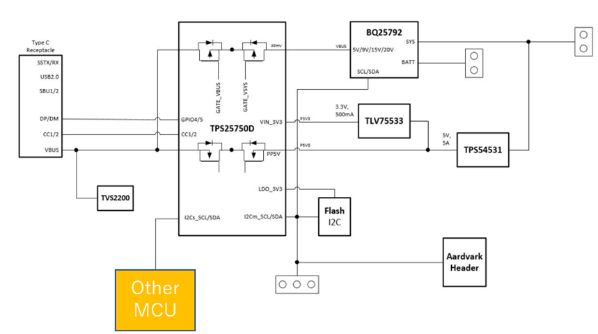
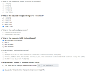
Our customer use USB-PD-CHG-EVM-01 and USB2ANY.
However, they can’t read suitable register value.
Even if they use USB-PD-CHG-EVM-01,
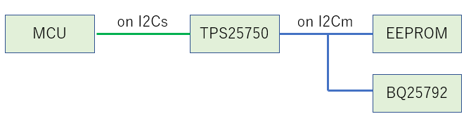
is it possible to execute pass-through mode using USB2ANY?
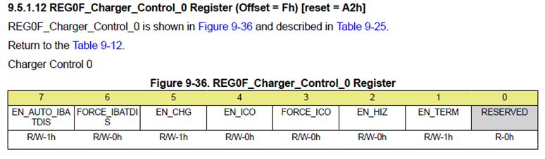
By the way, they tried to read to REG0F_Charger_Control_0 Register of BQ25792 on USB-PD-CHG-EVM-01 by USB2ANY.
However, the read result is " 0x04 0x00 0x00 0x00 0x00 ".
This value is incorrect because resister default value is 0x12.
If USB2ANY can support pass-through mode, could you please let us know appropriate method?
-----------
【Step1】
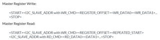
PD address | DATA1 register | #byte count | BQ address | BQ register | BQ #read bytes eg:
0x21 | 0x09 | 0x03 | 0x6B | 0x0F | 0x01
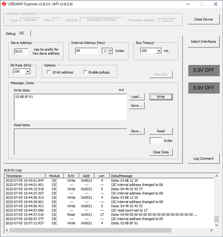
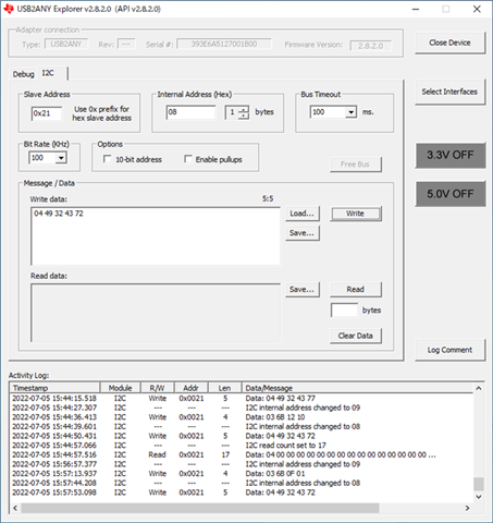
【Step2】
PD address | CMD1 register | #byte count | 'I' | '2' | 'C' | 'r'
0x21 | 0x08 | 0x04 | 0x49 | 0x32 | 0x43 | 0x72
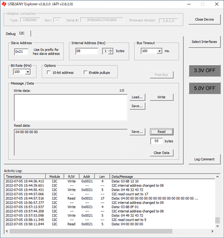
【Step3】
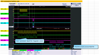
The read result is " 0x04 0x00 0x00 0x00 0x00 ".
This value is incorrect because resister default value is 0x12.
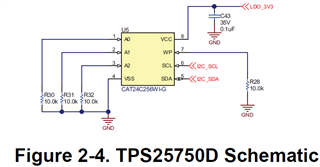
<BQ25792 datasheet>
-----------
Regards,
Hide