Our customer is having an issue with triggering the secondary side ASC (AI5 & AI6) with no voltage on VCC1 (never applying voltage to anything on primary side). These are the voltages that they are applying to the secondary/isolated side of the gate driver:
|
Pin |
Name |
Voltage to GND2 |
Note: |
|
36 |
DESAT |
0.00 |
measured |
|
35 |
VCC2 |
15.70 |
applied externally |
|
34 |
VCECLP |
-4.50 |
measured |
|
33 |
VBST |
0.00 |
measured |
|
32 |
OUTH |
-4.50 |
measured |
|
31 |
OUTL |
-4.50 |
measured |
|
30 |
VEE2 |
-4.50 |
measured |
|
29 |
CLAMP |
-4.50 |
measured |
|
28 |
GND2 |
0.00 |
measured |
|
27 |
VREF |
4.00 |
applied externally |
|
26 |
AI1 |
0.00 |
measured |
|
25 |
AI2 |
0.50 |
measured |
|
24 |
AI3 |
2.55 |
measured |
|
23 |
AI4 |
2.44 |
measured |
|
22 |
AI5 |
4.00 |
applied externally |
|
21 |
AI6 |
4.00 |
applied externally |
|
20 |
VREG2 |
-2.70 |
measured |
|
19 |
VEE2 |
-4.50 |
applied externally |
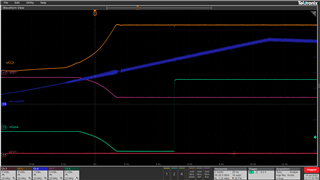
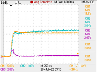
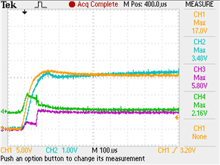
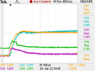
All voltages on the primary side relative to GND1 are 0 V as this side is not powered. I think I’m not understanding something. The intention right now is to trigger ASC on the secondary side while only supplying 15 V to VCC2 and then 3-4 V to AI5 and AI6.
Thanks,
Jeramie