Because of the holidays, TI E2E™ design support forum responses will be delayed from Dec. 25 through Jan. 2. Thank you for your patience.

This thread has been locked.

If you have a related question, please click the "Ask a related question" button in the top right corner. The newly created question will be automatically linked to this question.

ISO5852S: TINA Simulation Issues

Genius 15709 points
Part Number: ISO5852S

Hi Experts,

Asking assistance on this query raised by a customer:

We need to use the ISO5852S to drive a SiC MOSFET for an application. I am taking reference from the evaluation circuit:

/cfs-file/__key/communityserver-discussions-components-files/196/HVP017A_2800_001_29005F00_Sch.PDF

I see that the PWM logic is not translated to the high side of the driver.

Attaching the files as a zip (ISO5852.zip)

ISO5852.TSC - TINA Simulation file
C3M0015065K.TSM - MOSFET model
C3M0015065K.lib - MOSFET library (from which the MOSFET model above was created)
ISO5852S_TRANS.TSM - ISO model (downloaded from https://www.ti.com/lit/zip/sllm435)

Thank you.

Regards,
Archie A.

  • Hi Archie, 

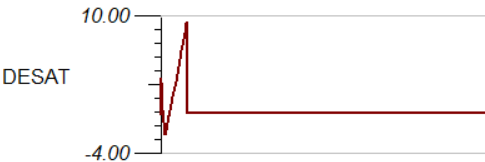
    I plotted DESAT and saw that it's triggered. That's why the output did not follow the input since the FLT pin fell to 0V. If you just want to investigate the switching behavior of this model, you can tie DESAT to COM. DESAT is only used when there's a short circuit event. 

    Also there are some discrepancies between the "source" rail and "GND2" rail

    Not related to this issue, but the input PWM should have 2.5V DC offset and amplitude of 2.5V, so the input is from 0V to 5V PWM

    As mentioned in another thread, we suggest switching to PSpice for TI for a better simulation experience. 

    Thanks, 

    Vivian

  • Thanks, Vivian!

    This really solved the issue.

    Regards,
    Archie A.