This thread has been locked.

If you have a related question, please click the "Ask a related question" button in the top right corner. The newly created question will be automatically linked to this question.

TPS7A20: About design Cin /Cout capacitance

Part Number: TPS7A20

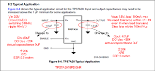
About TPS7A2018PDQNR (Vout 1.8V/ package X2SON),

1. We are thinking that select the Vin/Vout capacitance as below figure condition.

    Do you think that Is diagram condition no problem for meet our need spec?

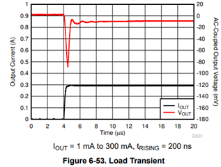
   Our need spec: Vout 1.8V tolerance within ±4%(even if load transient). load is 100uA max. Slew lare within 100mV/us.

2. If information is not enough for checking the problem, please teach it to me.

3. Besides, we would like to know calculating method Vin/Vout capacitance value.

   Could you teach the calculating method, please?

Best regards,

  • Hi Hosogai-san,

    A way to estimate the worst-case output voltage deviation is to assume that the load transient is a step function and calculate how much charge leaves the output cap before the LDO can respond and begin bringing the output back to its target. I'll first use an example from the datasheet to illustrate what I mean. 

    In Figure 6-53, the LDO responds to the transient in ~500ns. If we assume that the load is 300mA for the entire 500ns transient and with COUT = 1uF, the output voltage deviation would be (300mA * 500ns) / 1uF = 150mV. In the figure the output voltage deviation is ~90mV, so you can see that this is an overestimation because of course the load current is not the full 300mA for the 500ns period before the LDO responds. This adds a lot of margin already, so if your application meets this estimation then there will be enough margin to be confident that it will work in your real application. 

    For your application, you can tolerate up to 1.8V * 4% = 72mV total output voltage deviation. If we assume that the response time is the same (500ns), and again that the maximum load transient (0mA to 100mA) is 100mA for the full duration, then the output deviation would be (100mA * 500ns) / 4.7uF = 10.6mV << 72mV. This is plenty of margin to be sure that your specs will be met.

    Regards,

    Nick