


Hi Team,
I have a couple questions regarding the LM2731.
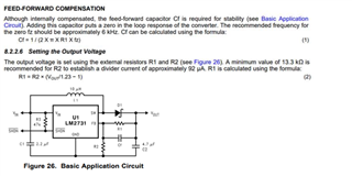
- The datasheet specifies that a compensation capacitor is to be used to form a zero at 6 kHz in the feedback path of the boost converter circuit.
In my design, the resistor in parallel is 200 kΩ, and so when the equation is solved, [2 * pi * 200,000 * 6,000]-1 equates to around 133 pF.
We have 100 pF and 150 pF on hand. Can we adjust the zero with 150 pF, equating to a little less than 6 kHz? I think it works out to around 5.3 kHz.
2. Also, in the datasheet, to set the output voltage, it uses the typical voltage divider feedback. It claims that the minimum value for R2 is 13.3 kΩ to establish 92 µA through the voltage divider. I chose a value that is near this, but which allows us to use an R1 value we have in stock. Our R2 is 15 kΩ. Are either of these an issue? What’s special about 92 µA?
I’m fairly certain these are a non-issue, this is a fairly low power situation and transients are not usually an abrupt step.
Thanks!
Connor
