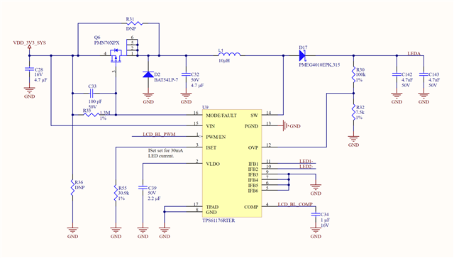
In the previous revision of our design we did not have the protection (PMOS) circuit and the MODE/FAULT pin was simply pulled to GND through a 1.3M resistor. In that original version the part behaved as expected.
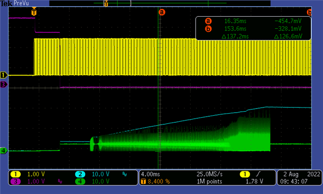
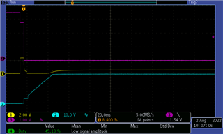
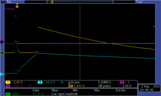
The PWM signal is a 1.8V level (true for both revisions) and we would generally just drive it high to 1.8V for full brightness. In this new revision, we added the protection (PMOS) circuit but otherwise left everything the same. Now when we drive the PWM duty higher than ~60% the boost and LED outputs turn off as if we set the EN to 0. We have tried low and high frequencies (200Hz and 16kHz) for the PWM signal but the behaviour remains unchanged. The parts we are using are from the same batch for both revisions. The latest revision circuit diagram is provided below.