This thread has been locked.

If you have a related question, please click the "Ask a related question" button in the top right corner. The newly created question will be automatically linked to this question.

TPS61087: Audible noise under PWM operation.

Part Number: TPS61087
Other Parts Discussed in Thread: , TPS61169

Dear team, 

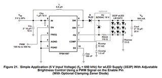
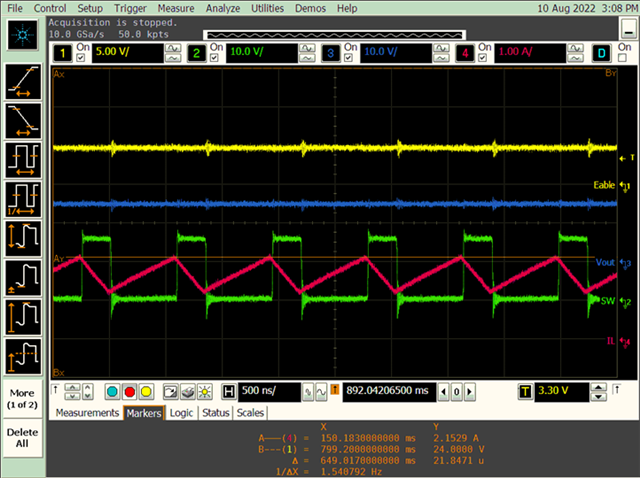
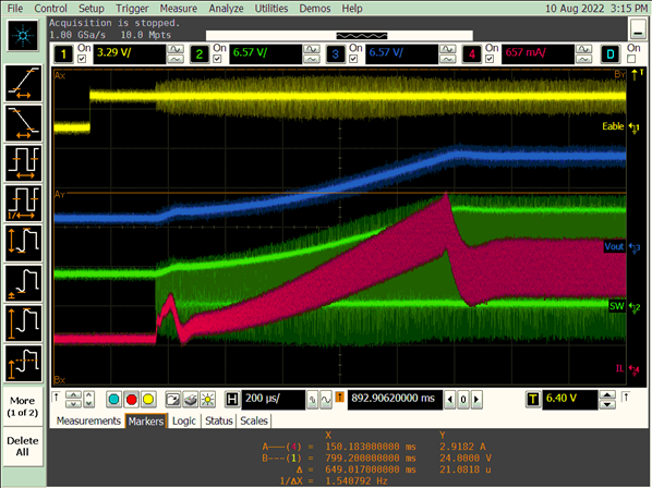
My customer are trying to develop TPS61087 for LED supply. but there is issue of audible noise under PWM operation. 

When they input 100% PWM, there is no audible noise but if they input below 100% PWM, there is audible noise.

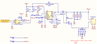
Please review below customer schematic and let me know your opinion regarding how can we debug this issue.

- output capacitor :4 x 10uF

Thank you.  

  • Hi Dino,

    The audible noise ranges from 20Hz~20kHz, it means that there may be ripple exist among the frequency range.

    Could you have a test of the inductor current and output voltage at the audible noise situation?

    If the low frequency ripple really exists ,you can then adjust your loop to restrain the ripple and audible noise.

    Thank you.

    Fergus

  • Hi Fergus, 

    Thank you for your comment. 

    I will check the inductor current and output voltage at the audible noise situation

    But why is there no audible noise at 100% PWM status? As mentioned above article, there is only the audible noise at below 100% PWM.  

    If layout or inductor ripple is cause of the audible noise, I think there has to be a problem at 100% PWM status. please let me know your opinion. 

    Thank you. 

  • Hi Dino,

    In my opinion, your 100%PWM means CCM mode or DCM mode, below 100% PWM  means skip pulse mode. Is that right?

     When the load become very light, chip come into skip pulse mode , it output a pulse of PWM then stop to wait the output voltage drop.

    In this mode, there could be low frequency ripple on some condition.

    Please observe the SW signal with current and voltage if possible.

    Thanks.

    Fergus

  • Hi Fergus, 

    I am sorry for confusing. 

    PWM input mean input of EN port. The customer application is LED power supply like below. 

    100% PWM is high status on EN pin. (12.7V 500mA output), To decrease LED current, they input 200Hz PWM on EN port. 

  • Hi Dino,

    Understand your application.

    There are some detail steps I'd like to advise you to do:

    1. check the noise source. The inductor or the capacitor or others?

     you can press on the suspicious device to check if the noise changes.

    2. if the chip works normally. If the current and voltage is stable?

    test the current or voltage of the device.

    3. If the device is reliable assembled? Is the parameter is suitable?

    You can change the device for another one(like other vender) to check if the issue exists.

    4. There may be layout problem. It can be complex to analysis.

    Thanks

    Fergus

  • Hi Fergus, 

    Thank you for your comment. 

    I tested 200Hz PWM signal on EN port using our EVM. but there is also a audible noise. so I think this is not layout problem. 

    If you have TPS61087EVM-317, would you please test this issue using our EVM?

    1. t when I press on devices, the audible noise doesn't change. But  I most suspicious of Inductor and our device. 

    2. the chip works normally. The LED Brightness Control is stable. 

    3. As mentioned above, our EVM also has problem. so I don't  think the parameter or assembly is problem. 

    At TPS61087 datasheet 21 page Figure21, I can see PWM range 100Hz~500Hz, Is it fixed range? 

    Can we use TPS61087 as LED supply with Adjustable Brightness Control using a PWM signal on th Enable Pin mentioned Datasheet? 

    Is there any other application note regarding LED supply? 

     Please let me know your opinion. 

    Thank you. 

  • Hi Dino,

    Firstly, the EN pwm frequency is among 100Hz to 500Hz.Because if below 100Hz,the LED may seems twinkle; the chip has a rise time of about 2ms(Css=100nF),so the frequency is recommended below 500Hz.

    Secondly, I feel sorry for not having EVM board on hand. Since we can repeat the issue on EVM, it will be easier to debug.

    It can been seen that the application's inductor, frequency and other parameters(seems same with EVM board) are different from the datasheet 21 page Figure21's usage.

    So can you have a try to change the parameter to 21 page Figure21,to see if there is a noise?

    Thanks 

    Fergus

  • Hi Fergus, 

    Because there is no LED module and 6.8uH inductor sample, I can't test with same parameter of 21 page Figure21 using our EVM

    But customer side, they already tested with same parameter of 21 page Figure21 using their board. there is also a noise too. 

    Do you mean if we use 1.2MHz switching frequency, can't we use TPS61087 as LED supply? 

    If the application introduced in the data sheet, don't you have the results of the test? Please check it again. 

    Please review it and let me know your opinion. 

    Thank you. 

  • Hi Dino,

    It may have no connection with the frequency.

    Since you have confirm the noise source is inductor, there is another improvement you can try.

    I notice that EVM board use the inductor with wound-rotor type. This kind of inductor is easy to cause noise issue.

    you can use the Integrated molding metal Magnetic inductor(maybe not professional name) instead.

    like TFM252012ALMA3R3MTAA for example.

    thanks 

    Fergus

  • Hi Fergus, 

    Thank you for your comment. 

    I understand your opinion and I will recommend to customer as your suggestion.  but I have one more question. 

    I notice that Other LED Driver like TPS61169 use the inductor with wound wire type also, but there is no noise issue.

    I am most suspicious of Inductor but I am also suspicious of our device. 

    As mentioned before article, If the application LED driver introduced in the data sheet, don't you have the results of the test or application note on BU side?

    Is there any other solution to this issue or debugging point on our device? Please let me know your opinion.  

    Thank you. 

  • Hi Dino,

        For TPS61169, it has a Programmable FB Voltage Using PWM Signal ,which will regulate its FB voltage due to PWM input.

    The chip regulate LED current by FB, not ON/OFF. It is different from TPS61087.

       Just to be sure ,please test the inductor current ,output voltage and SW on EVM board on noise situation. Upload the detail waveform if possible.

    After all, we can not ensure the parameter on EVM is suitable on the situation.

        For chip noise, you can use wire to take out the inductor. In this way, you can hear if the chip generates noise.

        Capacity also must be checked whether it is the noise source. 

     Thanks 

    Fergus

  • Hi Fergus, 

    I have tested using our EVM as your recommendation. 

    I used wire to take out the inductor. so Noise source is not the inductor. The audible noise is from board. it seems to come from output capacitor. 

    Below file is Enable, the inductor current ,output voltage and SW waveform of TPS61087EVM

    TPS61087 EVM test_E2E_220810.pptx

    Please review it again and let me know your opinion. 

    Thank you. 

  • Hi Dino,

     It seems that the loop is stable at start period and stable period.

     Since noise is come from output capacitor, you can try as follows.

    1. change the capacitor to smaller ones, like 4*10uF to 8*5uF, 0805 to 0603.

    2. change the placement of the capacitor. Place two capacitors at same position of front and back of the board may neutralize the vibrating.

    This may be a little hard to realize. 

    3. One effective method is to use Anti-Acoustic Noise capacitor like muRata ZRA and ZRB series. And the KAM series can be most effective but may be a little expensive that recommended  for urgent use.

    Thanks

    Fergus He

  • Hi Fergus, 

    Thank you for your comment. I will test again as your recommendation. 

    One more question. As you can see below, When Enable is high and 0.5A load , peak inductor current is 2.15A. But When enable is 200Hz 50% duty and 0.5A load, Inductor current peak is 2.91A. Please let me know your opinion regarding this difference. 

    Thank you. 

    <Enable high, 0.5A load> 

    <Enable 200Hz 50% dyty, 0.5A load> 

  • Hi Dino,

    The 2.91A peak current appears near the end of start time. During start time, the current not only apply for the LED load ,but also for the output capacitor to rise its voltage.

    The 2.15A peak current appears at the stable time. The output capacitor doesn't need additional input current. Inductor's peak current is obviously smaller than that during start time.

    Thank you 

    Fergus