This thread has been locked.

If you have a related question, please click the "Ask a related question" button in the top right corner. The newly created question will be automatically linked to this question.

TPS62913: Need to clarify the Phase margin requirement and schematic review of TPS62913

Part Number: TPS62913

Hi

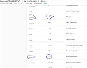
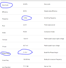
I have a query related to low phase margin (39 degree) with one of the Power rail that I have simulated and designed as well.

Generally it is recommended to go with more than 45 degree for stable system. In such case where the phase margin is less what can we do? 

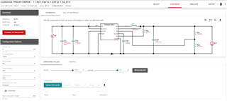
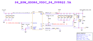
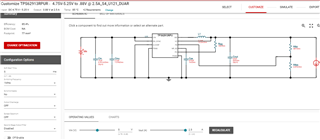
Sharing the design requirements and schematic, webbench simulation design and simulation results for your reference.

The design requirement is 

1. Vin= 5V (4.75V-5.25V) 
2. Ripple=10mV
3. Vout Tole.= 1% (8.8mV)
4. Iout= 2A to 2.5A


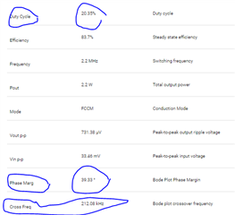
Now if I am changing the frequency from 2.2MHz to 1Mhz the phase margin is increasing. 

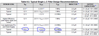
But in the datasheet it is mentioned that for Vout less that 3.3V and Vin=5V the Fsw= 2.2MHz.

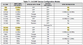
Now if I am connecting the S-CONF pin to ground to select 1MHz is it fine? 

Would you please check and suggest to improve the phase margin while maintaining the duty cycle?

  • Hello, 

    45 degrees of phase margin is a good rule of thumb, but not a hard requirement. If your system does not have large load steps, a lower phase margin may be OK. Using 1MHz for this condition is ok in most cases, although the output ripple will increase due to the increased current ripple in the inductor. The design will still be within your requirements, and you are not at risk of hitting current limit either. 

  • Hello Steve,

    Thanks for the clarification. I have one Power rail with below requirement.

    The design requirement is 

    1. Vin= 12V (11.4V-12.6V) , Vout=1.2V
    2. Ripple=10mV
    3. Vout Tole.= 3% (36mV)
    4. Iout= 0.8A to 1.2A

    While simulating this rail on Webbench, The duty-cycle is very less (9.98%). 

    Do we have any concern on this rail?  Please suggest.

  • Hello, 

    The duty cycle is low because you are converting from 12Vin to 1.2Vin, which is 10%.  As long as you do not violate the max min on time of 70ns, there is no issue with a low duty cycle.