This thread has been locked.

If you have a related question, please click the "Ask a related question" button in the top right corner. The newly created question will be automatically linked to this question.

LM5176-Q1: Inductor ringing problem when using comp components from the quickstart guide

Part Number: LM5176-Q1
Other Parts Discussed in Thread: LM5152-Q1, LM5176, CSD18563Q5A

E2E,

I have a good number of questions though my most pressing question has to due with the compensator components generated by the quickstart calculator and/or my interpretation of them:

Ranges:

IOUTmax = 6A

VOUT = 12V

VIN ranges from 7.5 to 12.6V

Questions:

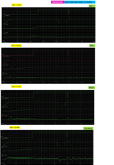
1.  When using the quickstart calculator (see attached) to determine compensator components I get unacceptable inductor current ringing with a fbw range of 1, 5, 10 and 15 kHz when VIN = 12.6V. Note: I do not have a ringing problem at a VIN of 7.5 or 10.8V:

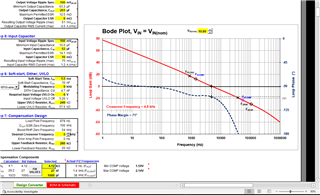
The part's datasheet suggests the fbw should be set to less than 1/3 of the RHP zero frequency (see equation 42).

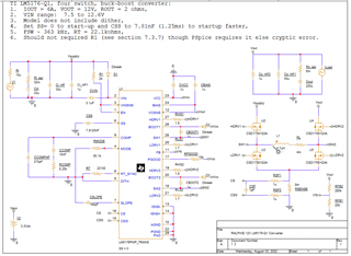
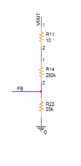
The current schematic (see attached "schematic.png") contains a snapshot for the comp components with an fbw of 10 kHz.

I also zipped the current state of the simulation in the attached zip file (assuming it is not to big for this forum).

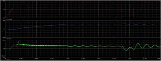
The results (see attached "ringing.pdf") pic contains the simulation results for the range of fbw listed above.

It is pretty clear in the worst simulations that the inductor current is ringing even before the load current step occurs.

Based on the quickstart loop gain, the phase margin should increase with decreasing fbw; however, ringing is low at 10 kHz then high again at 5 kHz.  There appears to be a sweet-spot which the quickstart loop gain plot does not cover.

Not sure if I made a mistake setting up the simulation though my setup appears to match the quickstart setup/entries.

Any thoughts how to get past this problem?

All steady-state operating points have to pass simulation before I can move forward with this part.  I had good results using the TI LM5152-Q1 quickstart calculator.

2.  LM5176 transient PSpice model requires resistor (R1 = 2kohms) from VIN/Vsupply to VISNS pin.
Datasheet: "7.3.7 Operation Above 40-V Input
For an application where input voltage is higher than 40 V, a 2-kΩ resistor in series with the VISNS pin is
required as shown in Figure 8-1."
My VIN/Vsupply ranges from 7.5 to 12.6 V so the 2kohm resistor should not be required.  

Is this a bug with the Pspice model or is the part's datasheet written wrong?


3.  PIN PGOOD appears to have an allowed ISINK(PGD) range:  2, 4.2, 6.5 mA (min, nom, max) (see part's datasheet, page 8)
The part's datasheet, figure 8-1, employs an RPGOOD of 10kohms connected to VCC which ranges from 6.95 to 7.88 V (min, max)
This is how I interpret the current through RPGOOD:
IPGOOD = VCC/RPGOOD = 0.695mA, 0.788mA which are both less than ISINK(PGD) min.
Perhaps I am misinterpreting ISINK on PGOOD.

How exactly should I interpret/determine if I have chosen an RPGOOD value which violates ISINK(PGD)?  
I'd prefer to connect RPGOOD to 3.3VDC instead of VCC.


4.  The part's datasheet and its corresponding EVM design appear to employ a tss (soft start time) of approximately 16ms.
A 16 ms start-up time seems pretty long (I am using a 0.1ms starup time for the LM5152-Q1 boost controller).

Is there a minimum recommended start-up time for this part?
What is the rational behind a 16 ms start-up time?  Perhaps some industry standard???


5.  The part's datasheet and its corresponding EVM design appear to employ filter components (RC) between the RSENSE resisor and
the CS/CSG pins.  The LM5152-Q1 datasheet has similar filter parts though does not appear to offer equations to properly size these
filter components.  It appears as though this part's datasheet, quickstart calculator nor EVM does not offer equations to properly
size these components either.
I do not believe that the part's datasheet offers enough info to properly size these parts and I am guessing there effect on
the final value of RSENSE.  Generally current sense filter increase the sense resistance i.e. RCS = (R1/R2)*RSENSE.

Would you please recommend a TI application note which properly sizes these current sense filter parts?


6.  FET gate resistance:
The part's quick start guide lists 1.5 ohms for all four fet's gate drive resistances.

How exactly were these values determined?  Perhaps TI has a good application note?


7.  FETs:
The part's quick start guide lists the TI CSD18563Q5A (buck leg) and CSD163215Q (boost leg).
The TI part LM5152-Q1 employs the following to help pick FETs:
Equation 1:  IG = 2*QG@5V*fsw and,
IG < IVCC_CL, where IVCC_CL = 100mA, and VCC ranges from 4.75 to 5.25
Know the range of VCC and the maximum QG@5V one can limit fet selection then make a final decision based on switching losses.

Does TI offer something similar for this part?
This part's VCC ranges from 6.95 to 7.88 V which limits VGS.

Perhaps I could use IHDRV1,2 (drive or sink) times a fets corresponding tr and tf, derive a minimum Q (Q = A*second) then
set that Q value as a minimum QG as a test for fets.

Does this sound correct?

Perhaps TI can recommend something similar to what part LM5152-Q1 does as listed above?


Thank you,

Craig

  18264.LM5176 Buck-Boost Quickstart Tool r1.0 12V.xlsm

  • Hi Craig,

    thank you for using the E2E forum.

    Let me try to answer your questions but as this is a quite long list I may need some more time.

    I try to come back within the next 2 days.

    Best regards,

     Stefan

  • Hi Craig,

    some first answers - see the index to map to the questions:

    2. if the Input is above 40V the series resistor to VISNS is mandatory - if V in is below it can be skipped but note that even if a spike is going above this level it can influence the device behavior. Having the resistor in does not neg. impact the device - so the better option is to add this resistor.

    Therefore the PSpice model might have been coded that way.

    3. This parameter specifies the on resistance of the Open collector switch but not the current which needs to be applied - so the resistor can and also should be higher to get a better low voltage level.

    4. the softstart time depends on the output cap and the load behavior during the startup phase.

    With the Softstart it will be avoided to trigger the over current due to the high inrush current into the output cap and load

    So this depend on your application.

    5. This filter should prevent high frequency noise to be captured by the current sense logic, typically the R is ~ 100 Ohm and C ~ 50pF

    Note: the Rs are in series to the input not to GND - so will not impact the Current sense Resistor

    6. This series Resistor are added to avoid ringing of the FETs - this is very application specific and needs to be measured on the final PCB. It is a good practice to add 0Ohm resistors onto the layout so that they can be added later easily without having the need for an PCB revision.
    It is also recommended to add Footprint for a snubber and reverse Diodes to the MOSFETs in case of ringing due to the layout.

  • Stefan,

    Thank you for looking into my questions.

    Concerning your response to:

    3.  (PGOOD): How did you determine that ISINK(PGD) is a collector on resistor spec?  The spec lists a min, nom and max current range for ISINK(PGD). There is a 0.4V "test condition" though I do not know what to do with that.

    Is there any more info to help convince me what how to limit the current going into PGOOD or should I just treat it like a normal PU resistor and shoot for a pin current around 50nA?  With this logic and assuming VCC at 8V and RPGOOD at 10kohms then pin current should be 8V/10kohms or 500uA (assumes transistor on resistance is much smaller than RPGOOD) which may be a bit high though I do not know because I do not understand the spec.

    5: (RSENSE filter):  Do you have any more information to convince me that RSENSE will not be modified by the filter components?  The circuit components connected to the CS and CSG pins are not provided so I do not know what is going on here.

    6.  (RG):  Thank you - I was planning on including at least 0 ohm RG (source) values and buck/boost DNP snubber components.  May include RG DNP "sink" components as well.

    But do you know at least how the RG values in the quickstart guide were estimated/determined?

    In the past I have used something like the following at least for the low side drivers:

    IG_L = ILDRV1,2 = (VCC-VT)/((RLDRIV_1,2) + RG_L))

    Where:

    VCC is spec'd from 6.95 to 7.88V,

    VT is a particular FET's threshold voltage (turn-on VGS), assume 2V for now,

    RLDRIVE_1,2 is spec'd at 1.7 ohms,

    and ILDRIVE1,2 is spec'd at 1.8 ohms (source).

    If one assumes an RG of 1.5 ohms (as in quickstart) then IG_L ~ 1.8 A which matches the spec.

    This becomes more accurate when all resistances are well known.

    There are probably better/more accurate ways of doing this though this is a good start.

    Thank you,

    Craig

  • Hi Craig,

    3. You need to read the datasheet it that way:

    Condition 0.4V at PGood then the current flowing into PGOOD pin is within the given limits.
    So this describes the Sink capabilities of the internal driver

    5. The influence of the filter is far, far, far, less then the accuracy variation of the sense Resistor. If you make the math you will find out easily, if you come to a different results, just share your math/notes and we can discuss your results with mine.

    6. There is good note here: https://e2e.ti.com/blogs_/b/powerhouse/posts/calculate-an-r-c-snubber-in-seven-steps

    Best regards,

     Stefan

  • Stefan,

    Your link for 6 above is for an RC snubber not gate resistance, RG.

    Craig

  • Stefan,

    I need a little clarity concerning your response to 3 above:

    The spec and EVM employ a 10 kohm resistor getting pulled up by VCC ~ 8VDC.

    Assuming any pin resistance is significantly smaller than 10 kohms then one may approximate the pin current to be:

    I = 8V/10kohms = 800 uA

    The spec lists ISINK(PGD) at 2, 4.2 and 6.5 mA (min, nom, max).

    800 uA is well below ISINK(PGD) minimum of 2 mA.

    How exactly does one interpret this?

    Seems like the pin current is below the minimum sink current i.e. a violation of ISINK(PGD)

    The pin current is below the minimum sink current i.e. not a violation of ISINK(PGD).

    If none of this makes sense then given an RPGOOD of 10 kohms and voltage of VCC (~8V) please detail what the pin current is and exactly how this does not violate ISINK(PGD) or does not violate the pin min/max current rating.

    I need a detailed response here.

    Thank you,

    Craig

  • Stefan,

    I do not know what the CS and CSG pins connect to internally so I do not know how to model the path of Rsense to the CS/CSG pins.

    Would you please provide me the math which convinces you that these filter components have little to no effect on Rsense?

    I need a detailed response here.

    Thank you,

    Craig

  • Hello Craig,

    This "filter" is not necessary if the controller can be placed close to the current sense resistor. If the traces (which should be routed as a differential pair, not using any of the existing polygons) are a bit longer, these components act as a termination for the "wiring" to the high impedance input of the error amplifier to improve noise immunity. Their values are dependent on PCB parameters.

    Regards,

    Harry

  • Stefan,

    Any luck with my original, most pressing question? (see #1 above).

    Craig

  • Hi Craig,

    I focused on the other questions so far.
    Can you give some more details on #1:
    - do you see this only in simulation or is this also in the real hardware.

    - have you tried to check if this changes with a higher or lower output cap.

    - what is the behavior if you extend the simulation time before the load step

    Best regards,

     Stefan

  • Stefan,

    1.  I am only at the simulation step,

    2.  So far I have not changed the size of the cap.  Assuming the loop gain response from the quickstart guide is accurate/correct then I should not need to (see attached "quickstart snapshot" pic),

    3.  I'll run a new simulation today (takes a while) though I imagine that I would see the same results.  So far at VIN = 12.6 V, the inductor current rings before and after the load step (see attached "ringing" pic at various bandwidths.  To me this sounds like a loop gain at a very low phase margin but I cannot know because TI does not publish internal component values which would allow one to verify/double check loop gain i.e. stability.

    Craig

  • Stefan,

    Simulation with a bandwidth of 5kHz and a load that switches about a msec later than the previous runs.

    Pretty much see the same thing - the inductor current rings.

    Craig

  • Stefan,

    BTW, decreasing Cout by 50uF increases ringing where as increasing Cout by 50uF decreases ringing though significant ringing is still present. 

    The inductor current is not able to track the stepped load.

    Craig

  • Hi Craig,

    let me try to do some more debugging, as you already mentioned the runs take quite some time.

    Best regards,

     Stefan

  • TI_Demo.zipHi Craig,

    there is something within your simulation setup. I just did rebuild your circuit based on the LM5176 PSpice reference design and this instability is not visible there.

    I have attached this version for your reference.

    Best regards,

     Stefan

  • Stefan,

    1.  I could not get your simulation to run.  It faulted out immediately.  Would you please double check that everything has been packaged together correctly?  I am not very good at resolving PSpice for TI problems.

    2.  Also, would you please provide a snapshot of the loop gain figure from the quickstart guide which corresponds to the compensator components that you used?  Seems like you may be using a fbw around 7 kHz,

    3.  I spent the day making slight tweaks to my original simulation.  The attached document captures each change on the corresponding simulation results.

    See pages 12 and 13 of the attached slides:

    Driving pin "EN" with a separate voltage source (vs tapping off of VIN with a voltage divider or direct) produces very different results i.e. inductor ringing gets replaced with large/fast inductor spikes.  Seems as though the current mode nature of this controller should prevent 30A spikes in inductor current.

    At this point I do not know what I am looking at.  Is this a problem with the parts PSpice model or is this how the part is supposed to behave?

    Thank you,

    Craig

    current state of simulation.pptx

  • Hello Craig,

    Stefan is out on vacation and Niklas is on a business trip.

    I will need to find someone who can support you next week.

    Regards,

    Harry

  • Stefan/Niklas/Harry/All

    I modified the TI evaluation simulation model (ideal switches, should be nearly the same simulation that Stefan posted earlier) to match my setup (VIN range, IOUT max, Cin, Cout, fbw, ...) and got nearly identical results to what I have been seeing with my "real switch" version (see "current state of simulation.ppt").

    In the attached (see "ideal switching simulation results.ppt") when VIN = 12.6V I am seeing very spiky inductor current, over the expect max given current mode control, after soft start which causes larger swings in Vout and PGOOD to toggle i.e. something is causing the simulation to fail at VIN = 12.6 V though work fine at VIN = 7.5V.

    Please let me know if you can see anything wrong with my setup and/or recommend a solution.

    Thank you,

    Craig

    ideal switching simulation results.pptx

  • Hello Craig,

    Monday is a bank holiday for us, so we will come back to you around mid of next week.

    Best regards,
    Harry

  • When someone has a minute please take a look at the problem that I am experiencing.

    Originally I had a problem with inductor ringing at VIN = 12.6 V though that was due to an odd EN pin bug.

    After correcting for the EN bug I started to see larger inductor current spikes at VIN = 12.6 V which should be prevented by current mode control.

    Please let me know what you find out.

    Thank you,

    Craig

  • Hi Craig,

    sorry the last reply got stuck.

    I tried to reproduce the behavior you have shown in the ppt but could not see this.

    6888.TI_Demo.zip

    I have attached the setup i have used. Maybe you check this and let me know the difference to your setup.

    Best regards,

     Stefan

  • Stefan,

    Assuming that you want me to compare the "steady-state" simulation:

    1. The simulation that you posted errors our immediately,

    2.  The simulation that you posted has an input voltage, VIN, of 7.5 V.  I do not have a problem with VIN at 7.5 V.  I have a problem at VIN at 12.6V,

    3.  Not sure why you added "RLoad" with "I_Load",

    4.  What bandwidth, fbw, are you using?

    The problem does not appear to be ideal vs non-ideal switches.  I think that there is either a problem with the spice model for this part or the quickstart calculation of compensator components / loop gain.

    If you look at "ideal switching simulation results.ppt" you can see that I started from the TI provided ideal switching simulation model and got the same results as with my actual switching model (see attached) documented in "current state  of simulation.ppt".

    Please look at the attached (actual switching model) simulation which is setup with a fbw of 5 kHz and VIN at 12.6V and let me know what I may be wrong with my setup i.e. I do not know why I am seeing large inductor spikes - did I mess something up or is this a spice model bug?

    Thank you,

    Craig

    0083.2_RALPHIE_LM5176_12V PSpice for TI.zip

  • Hi Craig,

    sorry, when making the zip file the updates from PSpice had not been written back to the hard disk, so it zipped an older file version.

    Therefore you saw the error.

    I left RLoad in and made it large to not need to remove it - it has no function

    I used your setting - copied the info from your schematic

    -> when doing Steady State simulations you need to initialize the output caps otherwise you will see a high inrush current.

    This inrush current triggered the overcurrent and restarted the SMPS circuit. This resulted in the fluctuation you have seen in the output voltage.

    1070.TI_Demo.zip

    In your real hardware or startup simulation you need to set the SS cap to a proper value.

    you can also check the voltage at CS input to not reach the current limit depending on the mode of operation.

    Best regards,

     Stefan

  • Stefan,

    I was able to "corrupt" (large inductor current spikes) your simulation at VIN = 12.6 V by changing your simulation settings to match mine and I was able to fix my simulation at VIN = 12.6 V by changing my simulation settings to match yours.

    The problem was not an individual component or ideal vs actual switching issue but rather a simulation setting issue.

    See attached "update simulation settings.ppt" for detailed explanation/steps.

    Note: I updated your simulation schematic to more closely match mine.

    Seems like the solution is to use the simulation settings employed by the evaluation simulation model:

    www.ti.com/.../LM5176EVM-HP

    Question:

    Does TI have a general recommendation for PSpice for TI simulation settings or should one generally match what is in the evaluation simulation model?

    Thank you,

    Craig

    update simulation settings.pptx

  • Hi Craig,

    thank you for the info and the detailed report.

    I am not aware that we have some recommendation for that.

    I will discuss this with the PSpice team and try to get more information or check if we can give some recommendation for settings to be used.

    But I expect that this will take some time (some weeks), esp. if some new documentation needs to be done.

    Best regards,

     Stefan

  • Stefan,

    What is the function of 10 ohm resistor in the feedback path for this parts evaluation simulation model (see attached pic)?

    Is this an injection resistor/port to perform Bode loop gain measurements?

    Thank you,

    Craig

  • Hi Craig,

    this is a part which is used on the real application PCB to do Bode plot measurements. In that case it is used as injection resistor.

    For a Simulation it has not function but to have the same schematic for simulation and final application this is often/sometimes added here as well.

    Best regards,

     Stefan

  • Hi Craig,

    I have not see an update in this thread for the last 12 days.

    So I assume this can be closed. If there is sitll something open just reply to reopen it.

    Clicking on the resolved button helps to maintain this forum.

    Best regards,

     Stefan