Other Parts Discussed in Thread: BQ500210,
Reference case # CS1183495.
Good evening. We recently acquired the BQ51025EVM-649 wireless receiver module to replace an older model (BQ51013EVM-725) that we use for testing. We use the receiver solely to measure the output when the unit is powered from any Qi enabled transmitter and an increasing load is applied. The transmitters used are units that are commercially available and may support even up to 15W.
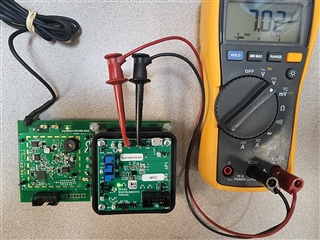
The (BQ51013EVM-725) was only capable of providing a 5W output (5V @ no load) and we could easily connect the load to J3 (OUT) and GND. So we purchased the new evaluation board since it supports up to a 10W output. When powering the BQ51025EVM-649 from a Qi enabled transmitter, the FOD led was illuminated and the measured output at no load was 7V, measured on J3(OUT) and J4(GND) pins. Could you assist in explaining why the (LED) may have been illuminated and why the output was defaulted to 7V? It was assumed that the receiver would at least default to low power mode and in that case the expected output would have been 5V. Could you suggest how we may configure the receiver to switch between low power (5W) and medium power (10W) modes? Could this be accomplished by making physical adjustments at the board level? Attached you will find an image of the setup when tested with the old TI (BQ500210EVM-689) transmitter. Any assistance/suggestions would be greatly appreciated. Thank you in advance for all your help.