This thread has been locked.

If you have a related question, please click the "Ask a related question" button in the top right corner. The newly created question will be automatically linked to this question.

TPS61040-Q1: Output Voltage dip occur when the LDO is turned on

Part Number: TPS61040-Q1
Other Parts Discussed in Thread: TPS61040

Hi,

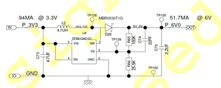
we are using the TPS61040-Q1 Boost converter for converting the 3.3V to 6V. Please find the schematics

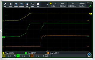
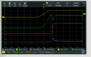
Attached the power sequence of this converter

The Yellow color represent the input voltage which is 3V3. The green color represent the (TPS61040-Q1) Boost output which is 6V0. This 6V0 is going to input of LDO(LOAD) which output is 5V0. The Violet color represent the Load current of Boost

Here we can see that the the TPS61040-Q1 output voltage is drop when the LDO turn on. 

Could you please give the solution for the same as earliest possible.

Thanks & Regards,

Thangaprabu S 

  • Hi Thangaprabu,

    It seems TPS61040 has a bad dynamic at start.

    It may be two reasons:

    1. TPS61040 has a soft start s starting from Ilimit/4 for 256 cycles, to Ilimit/2 for the next 256 cycles, and then full current limit.

    The LDO start just at the Ilimilt/2 period ,so the voltage drops when current limit is lower than load current. 

    You can try to delay the start time of LDO to see if it will occur again.

    2. The parameter is not reasonable. you can refer to this paper to check the parameter is suitable.

     tps61040.pdf.

    Thanks 

    Fergus He

  • Hi Fergus He,

    We tried to create the delay in turn on of LDO. But still the output voltage dip of TPS61040 boost converter exist.

    Attached the screenshot for the same.

    Please clarify.

    Thanks & Regards,

    Thangaprabu S

  • Hi Thangaprabu,

    the waveform shows that it is reason 2.

    Your current parameter ,the max on time should be Ilimit*L/Vin=0.6us,which is far small than the max on-time 6us.

    Small On time means there must be more duty cycles to converge energy from Vin to Vout, which causes the voltage dip.

    So I advise you to enlarge your inductor. You can choose 10uH,22uH even 47uH to satisfy you voltage dip spec.

    Thank you 

    Fergus He

  • Hi Fergus He,,

    I have done test with parameter change as you recommended.

    The Inductor is changed to 22uH & the output capacitance is also changed to 30uF. Along with created the delay to turn ON the LDO. Due to this LDO always on after fully ON of Boost converter.

    But the issue is not fixed till now. please refer the below attachment. The Boost output voltage is dipped again.

    The LDO load current is also measured. Due to the 10uF in LDO output line, the LDO output inrush current seems to be 698mA. LDO used is don't have the control of rise time. For this case, how we can avoid the voltage dip of boost converter during turn ON

    Thanks & Regards,

    Thangaprabu S

  • Hi Thangaprabu

    Thank you for your waveform.

    There is one more waveform I hope you to capture is that the inductor current of TPS61040 during the voltage drop.

    Please  zoom the current waveform to ensure we can see the current clearly.

    Best Regards

    Fergus He

  • Hi Thangaprabu

    I think over the problem, the result maybe can not improve much.

    At the start of LDO, the inrush current is near 380mA, with output voltage of 6V, the power output is near 2.4W;

    the input current peak is near 400mA, input voltage is 3.3V,input max power is nearly 1.2W, much small than output power.

    So the output voltage will drop definitely.

    The only way to decrease  the voltage drop is enlarge output capacity.

    You can calculate the output voltage drop like this. 1/2*Co*kd*(U1*U1-U2*U2)=(Po-Pin)*Dt

    Co is output capacity,30uf;kd is the capacity decay coefficient, usually less than 50%

    U1 is initial Vo,6V;U2 is finish Vo, need to be know

    Po is output power,2.4W; Pin is input power,1.2W;Dt is the inrush time, nearly 0.1ms;

    Best Regards

    Fergus