To whom it may concern
I'm about to finalize a design initiated by a former colleague who has based his power supply design on a LMR14020SDDAR switcher, which I’m not familiar with. I believe the switcher design is ok (based on webench), however I’m concerned about the input stage.
Description:
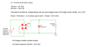
Power to the LMR14020SDDAR will be supplied from a 24VAC (18 VAC to 26 VAC, 50Hz) transformer output via a full bridge rectifier with a total of 110uF smoothing capacitance.
The full bridge rectifier is realized using 4 pcs schottky rectifier diodes, On Semiconductor SS24FL, Vf=0.55V.
Taking into account the voltage drop in the full bridge rectifier diodes the minimum theoretical rectified and filtered dc voltage is 24.4 VDC.
Switcher design:
Vin: 20VDC to 36VDC
Vout: 9.5V
Iout: 0.9mA(max)
Efficiency: 88%
Power_in: (0.9 x 9.5)/0.88 = 10W equivalent to a 59.5 Ohm load resistor.
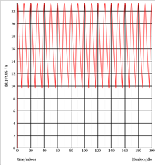
A simple simulation of the input stage equvalating the switcher with a 59.5 Ohm resistor shows there is a lot of ripple (13Vpp) on the input voltage to the switcher, which does not surprise me, the 110uF smoothing capacitor is probably a factor 10 to 20 too small in order to keep ripple less than let’s say 10%.
The question is if the switcher design can accommodate this magnitude of input ripple?
If it a problem the obvious solution is to add a bigger smoothing capacitor, however, this probably means that we also have to redesign the enclosure since board space is very limited and these capacitors (1000..2200uF) are quite big.
Any inputs will be appreciated.