This thread has been locked.

If you have a related question, please click the "Ask a related question" button in the top right corner. The newly created question will be automatically linked to this question.

LM5023: Operational Frequency Range and Compensation Question

Part Number: LM5023
Other Parts Discussed in Thread: UCC28740, UCC28720
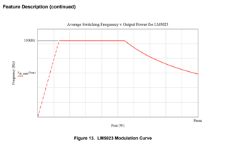
  1. I generated a Mathcad sheet for datasheet example. Then updated it with my design. I am noticing that my High line (275vac and 400vdc) Frequency  at  current limit  , I am above 130khz or close to it, However in datasheet example high line frequency is only 62khz. Is there any general guidelines need to be followed here?. Since max frequency is 130khz I assume for higher frequency requirements, after turn off, the delay extends until 130khz is met and next cycle start. The losses associated with ringing is the only drawback here waiting for 130khz?

Please review attachments

  1. In Lm5023 datasheet Eq 33 introduces the term Freq_comp
  2. In layman's terms , Can anyone explain the purpose of calculating Freq-comp
  3. In my design the comp value iam getting is >130khz. Can I proceed with R external and Rff calculations with the value (196khz) I am getting ? 

Please review attachments

/cfs-file/__key/communityserver-discussions-components-files/196/F_2D00_Comp-and-Frequency-High-line-question.pdf

/cfs-file/__key/communityserver-discussions-components-files/196/Datasheet-Example-mathcad.pdf

/cfs-file/__key/communityserver-discussions-components-files/196/My-Design-Mathcad-Rev-1.0.pdf

/cfs-file/__key/communityserver-discussions-components-files/196/ac-voltage-details.pdf

  • Hello,

    I reviewed the LM5023 data sheet and the design is limited to 130 kHz maximum. However, this should not occur at full load. 

    I reviewed your files and your input range is 54 to 400V.  This is roughly 7.4 to 1 where the data sheet example is 2.5 to 1. 

    To use the LM5023 in a QR flyback requires the design be operating in full QR at maximum load.

    The design example has a frequency 44.725 kHz at minimum input voltage.   The design will go into DCM at 130 kHz.   The maximum input range in this example with margin is 130 kHz*0.9/44.725 kHz to 1 = 2.6 to 1.  To get a little more range out of the design you could lower the switching frequency at the minimum input voltage.

    Since you have such a wide input range.  You could consider using the UCC28740 DCM flyback controller instead.   This device can  be designed for an input range of 9 to 1.  The following will bring you to the data sheet of the UCC28740.  If you have questions on how to use this device please repost in the e2e with the UCC28740 in the title.  https://www.ti.com/product/UCC28740

    The following link will bring you to an application note that discusses how to design DCM flyback controllers using the UCC28720/2 devices.  The same information applies for the UCC28740.  You may find this information useful as well.

    https://www.ti.com/lit/an/slua781/slua781.pdf

    Regards,

    Regards, 

  • Thank for reviewng the design. Let me look in to UCC28740 

  • Since major part is answered here, I will close this and ask F-Comp question as a seperate item