This thread has been locked.

If you have a related question, please click the "Ask a related question" button in the top right corner. The newly created question will be automatically linked to this question.

LM5143-Q1: schematic review support

Part Number: LM5143-Q1
Other Parts Discussed in Thread: LM25143-Q1, LM5143, LM25143

Hi Team,

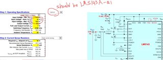
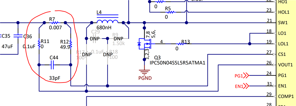
Can you help to double check the schematic of U4002 (LM5143-Q1) ?

The quick calculation toll result and FET spec are in the Zip file already.

mpci_ti_parts_20220811_pwr_Kai review.pdf

snvc229f.7z

Thanks!

Kai

  • Hello Kai,

    The  QS tool inputs do not match the schematic.  The QS tool is configured for a 60V input single output interleaved design, the schematic for U4002 is configured for a dual output design.  Please feel free to reopen thread with the correct QS tool attached so I can check design and specification of your design .  Thanks,

    David.

  • Update!

    Hi David,

    Thanks for your reply!
    But I checked the attached QS tool what I attached, it have correct setting I think so... Can you check again ?
    LM(2)5143-Q1 quickstart design tool - revB2-Kai adjust_20220816.xlsm

    Only the device name should be fix,  customer will use LM25143-Q1 instead of LM5143, but I think this doesn't impact much.

    Customer design spec is 12Vin (stable, not from battery), output 3.3V / 7A TDC, 13A peak, so they will using Single-Output Interleaved Operation.

    Thanks!
    Kai

  • Hello Kai,

    Sorry for the confusion.

    Couple of points for feedback on the schematic.

    1. I would install an RC for the current sense inputs as shown in example below.

    2. install an Electrolytic to ensure the input filter is well damped.  You may not use an input filer, but if long leads or even long traces are inductive this will need to be damped.  link below shows how to dampen, typically use an electrolytic bulk cap whos C value is 4 x the CIN ceramics used at the input and the ESR if Sqrt(L/CIN_ceramic) if you do not have an inductor per se use an estimation of a few hundred nH for long leads.  You may not need to dampen if the inductance in very low but it wont hurt to install place holders just in case.  

    3. Auto Applications typically require about 42V to handle load dump conditions, your FETs are not rated to for this.  Please select higher VDS rated FETs if the design is required to withstand 42V.

    Hope this helps?

    David.

  • Hi David,

    Thanks a lot for your support on this.

    Below is my reply regarding your comment. 

    1. I will  follow your to share the RC filter suggestion to customer.

    2. You might forget to input the "Link", Can you check again ?  Ha Ha~ Thanks!

    3. Yes, I know Auto Applications typically require about 42V to handle load dump, but in this application, the Vin 12V is from another POL(at another board, and connect to LM25143 board by a cable) instead of a battery, So I think the MOSFET VDS here is fine. 

    Thanks a lot!
    Kai

  • Sorry Kai,

    Please see link below for more details on input filter damping.

    https://www.ti.com/lit/an/snva538/snva538.pdf

    David.

  • Hi David,

    Got it!

    Thanks a lot!

  • Hi David,

    For the Electrolytic at input for damped, ifs that ok if customer use a POSC(Tantalum-Polymer) instead of a Bulk cap?

    So now customer MLCC at Vin is about 40uF, it will suggest customer add a 150uF or 220uF at the input side before those MLCC cap, am I right?

  • Hello Kai,

    Correct, Damping Cap will need to be 4 times greater than the Cin ceramics, 40uF should be adequate **.  The ESR will need to be equal to SQRT(Lparasitc/Cin_Ceramc)  as long as its ESR is close to the calculated value you will be OK. 

    **40uF of ceramics at the input is fine, as long as it meets the RMS ripple current rating requirements of the converter.  You are benefiting for a dual phase as  with timing 180 degrees apart as there will be ripple current cancelation reducing the total RMS ripple currents the ceramics will deliver.

    David.

  • Hi David, 

    Sorry that I can't understand what is  "The ESR will need to be equal to SQRT(Lparasitc/Cin_Ceramc)" ?

    Can you based on customer design 10uF*4 MLCC at input as a example then show my how to design a POS or Bulk cap here? I know the cap C value can be 150 or 220uF, how to choose the ESR parameter ?

    Thanks a lot.....

    Kai

  • Hello Kai,

    Assuming you do not have a physical inductor installed at the input.  Assuming you have long PCB trace/wires, assuming this amounts to 200nH of inductance the calculation is as follows without taking into account de-rated capacitance of your ceramics.

    SQRT(200nH/40uF) = 0.071ohms for the ESR. If your damping cap has 10s of milliohms of ESR you should be fine as shown in this example given.

    Hope this helps?

    David.

  • Hi David,

    Understood now!  Thanks for your explanation.