This thread has been locked.

If you have a related question, please click the "Ask a related question" button in the top right corner. The newly created question will be automatically linked to this question.

BQ76930: What is the voltage measurement logic of BQ76930?

Part Number: BQ76930

Hi Team,

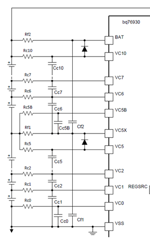
There is a interesting situation here: when Rc increase suddenly(from 1k to 56k), the voltage measurement will lost accuracy(lower or higher, nobody knows). And it should be noticed that the battery voltage remains constant, which is measured by a multimeter.

So, there are some questions as follow:

    1. Is the voltage measurement achieved by detecting the current flowing into VCx? If yes, then the VC1/2/3/4/6/7/8/9 have both current flow out and flow in, what is the voltage measurement logic of BQ76930?

    2. Is the voltage measurement of different battery cell synchronous or asynchronous?

    3. Does the "Integrated cell balancing" works automatically? 

    4. If the accuracy is lost due to impedance matching, what should be the Rc range of the reference?

Thanks & Regards

Francis Jiang

  • Hey Francis,

    1. There is a very small current going into the VCx pins. Current flow and measurement logic are described in section three of the app note linked below. 

    https://www.ti.com/lit/an/slua749a/slua749a.pdf?ts=1660763088934&ref_url=https%253A%252F%252Fwww.ti.com%252Fproduct%252FBQ76930 

    2. Cell measurements are done synchronously within cell groups and asynchronously between them.

    3. Integrated cell balancing is not enabled by default.

    4. There are limits on the input filter resistor or capacitor. This may be why you are seeing measurement issues. See the screenshot below taken from Table 7.3 of the datasheet.

    Thanks,
    Caleb

  • Hi Caleb,

    Thank you for your prompt reply! But the app note you provided does not explain in detail the measurement principle inside the chip. Maybe it can be equivalent to a resistor, a capacitor, or an op amp?

    Here is a real case:

        1. VC5, VC5B Node Front end (to Core) Impedance suddenly becomes larger, will cause abnormal voltage jumps of cell3 and cell4, with no fixed amplitude or direction of jump;

        2. Initial Rcs are set to 1k. Individually increase Rc of VCO, cell 1 voltage becomes low; individually increase Rc of VC1, both cell 1 voltage and cell 2 voltage are unchanged; individually increase Rc of VC2, cell 2 voltage becomes low and Cell3 voltage becomes high; individually increasing Rc of VC5, cell3 voltage becomes low.

           Therefore, Is sampling principle different within a cells group? Is sampling principle different between cell groups? Which channels are exactly the same?VC1 and VC5? VC6 and VC10?

    1. There is a very small current going into the VCx pins. Current flow and measurement logic are described in section three of the app note linked below. 

    Besides, according to datasheet, the typ of Idnom is ±2.5uA, why there is a negative value? This means that current will flow out from the VC5X.

    Thanks & Regards

    Francis Jiang

  • Individually increase Rc of VCO, cell 1 voltage becomes low; individually increase Rc of VC1, both cell 1 voltage and cell 2 voltage are unchanged; individually increase Rc of VC2, cell 2 voltage becomes low and Cell3 voltage becomes high; individually increasing Rc of VC5, cell3 voltage becomes low.

    increase Rc from 1k to 56k.

  • Hey Francis, 

    The device uses an ADC (op amps) to measure voltages. This is explained in section 8.3.1.1.2 of the datasheet.

    Sampling principles are not different within cell groups or between cell groups. Cell group measurements happen at a different time. Going beyond the maximum Rc value can cause the part to function improperly. Do you have a schematic that we can look at regarding the VC5 and VC5B case?

    Current can flow out of the VC5x pin.

    Thanks,
    Caleb

  • Hi Caleb,

    This is the schematic that I mentioned last time:

    Where Rcx = 1k, Rc5B = 1k, Rf = 100, Ccx = 0.5uF, Cc5B = 0.5uF, Cf = 10uF. Between Rc0 and Rc1 is cell1, between Rc1 and Rc2 is cell2, etc.

    Further, the real case can be updated as follow:

        1. Increasing Rc5, Rf1, Rc5B from 1k to 56k, the voltage measurements of cell3 and cell4 have an abnormal jump, with no fixed amplitude or direction;

        2. Increasing Rc0 from 1k to 56k individually, the voltage measurement of cell1 becomes low; increasing Rc1, both the voltage measurements of cell1 and cell2 are unchanged; increasing Rc2, the voltage measurement of cell2 becomes low and cell3 becomes high; increasing Rc5, the voltage measurement of cell3 becomes low.

    By the way, in the above cases, the battery cell voltage are unchanged according to a multimeter.

    Current can flow out of the VC5x pin.

    What is this situation? Why current can feedback into a battery from the device?

    Thanks & Regards

    Francis Jiang

  • Hey Francis,

    Rc5B is between two cell groups on the device, so I think it's behavior compared to the other Rcx pins is okay. I'd imagine that going above the max recommended resistor value for that pin could cause some issues. 56Kohms should not be used on the Rcx pins. 

    Only thing that comes to mind is some sort of leakage current out of VC5x. Sometimes we put parameters on there because it is possible for the part to have current flow into it, but that does not necessarily represent normal pin behavior.

    Thanks,
    Caleb

  • Hi Caleb,

    Thank you for your patience. These responses are helpful, and I will test and simulate further. Any progress will be shared with you. Thank you again for your support.

    Best Regards

    Francis Jiang

  • Hey Francis,

    No problem. Glad I could help.

    Thanks,
    Caleb